15
16
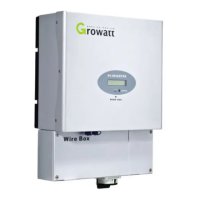
There must be sufficient clearance between the individual inverters to
ensure that the cooling air of the adjacent inverter is not taken in.
If necessary, increase the clearance spaces and make sure there is enough
fresh air supply to ensure sufficient cooling of the inverters.
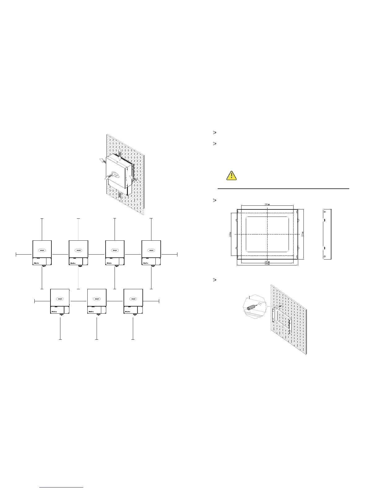
5.3 Mounting the Inverter with bracket
WARNING
In order to avoid electrical shock or other injury, inspect
existing electronic or plumbing installations before
drilling holes.
The dimension of bracket as follow
Using the mounting frame as a template, drill holes as illustrated in
image.
Ambient dimensions of one inverter
Ambient dimensions of a series inverters
M in 30cm.
Min.50cm
M in 30cm.
M in 30cm.
M in 30cm.
M in 30cm. M in 30cm. M in 30cm. M in 30cm.
M in 30cm.
Min.50cm
Min.50cm
Min.50cm
Min.50cm
Min.50cm
Min.50cm Min.50cm
Min.50cm
Min.50cm
Min.50cm
 Loading...