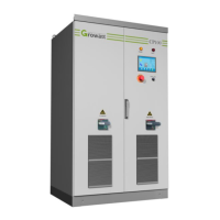
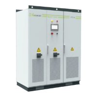
The Growatt CP250 is a PV grid-connected inverter designed for efficient and reliable operation in solar power generation systems. It is suitable for industrial, commercial, and residential applications.
Function Description
The Growatt CP250 inverter plays a crucial role in photovoltaic grid-connection systems by converting DC current generated by PV modules into AC current and feeding it into the public grid. It features advanced DSP control technology, which ensures high efficiency and wide MPPT voltage range. The device is designed for simple operation and easy maintenance, with a protection function that enables PV systems to operate more reliably.
The inverter supports various communication methods, including RS485 and Internet communication, allowing users to monitor the operating status of the PV power generation system. It provides single-machine and multi-machine control programs, along with diversified communication interfaces.
Important Technical Specifications
PV Input Quantities:
- VMAX PV (absolute maximum): 1000 d.c. V
- PV input operating voltage range: 450-1000 d.c. V
- Maximum operating PV input current: 635 d.c. A
- ISC PV (absolute maximum): 635 d.c. A
- Max. inverter backfeed current to the array: 635 a.c. or d.c. A
AC Output Quantities:
- Voltage (nominal or range): 400 a.c. V
- Current (maximum continuous): 360 a.c. A
- Frequency (nominal or range): 50/60 Hz
- Power (maximum continuous): 250 kW (or VA with PF)
- Power factor range: >0.9
- Maximum output fault current: 400 (RMS) a.c. A (peak and duration), or RMS
- Maximum output overcurrent protection: 400 a.c. A
General Specifications:
- Weight unit: 1600 kg
- Ingress Protection: IP20
- Environmental category: Indoor
- Suitability for wet locations: Not
- Pollution degree: II
- Elect.protection class: Class I
- Overvoltage category: Category III for AC output, Category II for DC input
- Mains connection: Permanent connection
- Transformer info: Without isolating Transformer
- Insulation class: Class H
- Operating Temperature Range: -25 to +55 °C
- Dimensions (WHD): 16002100850 mm
Usage Features
Installation:
The inverter requires installation on an even ground with fire-retardant material or a channel steel support structure. It should be installed indoors, away from direct sunlight and rain, in a well-ventilated and clean environment. Due to potential noise during operation, it is recommended to install it away from residential quarters. Adequate space (at least 1.5m in front) must be reserved for maintenance, emergency access, and ventilation.
Wiring:
- DC Side Wiring: The positive and negative terminals of the PV array must not be connected in reverse. A multimeter should be used to determine polarity before connecting to the inverter's input ends. The DC side wiring involves stripping cable insulation, crimping copper noses, and installing heat shrink tubing.
- AC Side Wiring: When connecting to the AC grid, the circuit breaker at the AC side must be cut off to ensure no electricity in the AC wire connecting to terminals. The AC connection cable order must be verified, and similar steps for stripping, crimping, and heat shrink tubing apply.
- Earthing: The inverter must be earthed for safety. The earthing cable should be at least 185mm², and the earthing resistance must meet IEC standards.
Operation:
- Power-on Procedures:
- Screw the handle of the circuit breaker at the AC side to "ON".
- Screw the handle of the circuit breaker at the DC side to "ON".
- The inverter takes about 10 seconds to initialize, and the "POWER" LED lamp will illuminate.
- If DC voltage is below 450Vdc, the touch screen will show "Waiting" (standby).
- If DC voltage is above 450Vdc and grid conditions are met, the inverter will automatically switch to "Normal," and the "OPERATION" lamp will be on.
- Automatic Power-on: The inverter powers on automatically when both DC and AC power-on conditions are satisfied. It also restarts automatically after a DC input or AC grid fault is cleared.
- Manual Power-off: The inverter can be powered off manually using the "OFF" button on the panel, which stops energy transmission to the grid. After manual power-off, the machine must be powered on manually.
- LCD Display: The LCD control panel provides real-time data, power curve, and energy yield figures. It allows users to view operation data, history information (faults, warnings), system settings (language, time, manufacturer info), and turn the inverter ON/OFF.
Safety Instructions:
- DANGER: Indicates a high level of risk that could result in death or serious injury if not avoided.
- CAUTION: Indicates a potential risk that could result in equipment malfunction and property damage if not avoided.
- WARNING: Indicates a potential risk of electric shock or fire hazard.
- Emergency stop buttons are available and must be functional.
- All electrical connections must comply with local electrical operation standards.
- The inverter must not be damaged if input or output terminals are incorrectly plugged.
- Electrostatic discharge can cause damage to internal components.
- The inverter cabinet must be free of tools, spare parts, and conductive dust.
- During transportation, lifting equipment and personnel must be qualified. The inverter should be placed vertically, and inclination should not exceed 10 degrees.
Maintenance Features
Routine Maintenance:
- Dust Screen Replacement: The dust screen should be cleaned regularly. The procedure involves opening the front and back covers, removing the old dust screen, inserting a clean one, and fixing the cover back in place.
- Regular Checks (Monthly):
- Check for dust, moisture, or condensation inside the cabinet.
- Check cable connections and tighten screws if necessary.
- Check warning labels and replace if needed.
- Manually check AC and DC circuit breakers.
- Check the emergency stop button and LCD stop function.
- Read data from the data logger.
- Clean the heat sink of the power module.
- Regular Checks (Weekly):
- Check for abnormal sounds during inverter operation.
Maintenance Safety:
- All maintenance operations must be performed with the DC and AC sides of the inverter, PV module, and AC distribution cabinet switches disconnected.
- Maintenance should only proceed after AC and DC are disconnected for at least 5 minutes to avoid electric shock.
Waste Disposal:
The inverter's components meet environmental protection requirements. Users must dispose of the inverter in accordance with relevant laws and regulations.