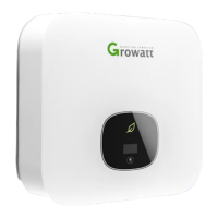
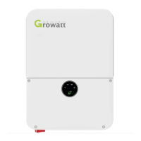
MIN 2500-6000 TL-XH
Quick Guide
Installing the Device
Connecting Cables
3.1 Installing the PV Input Power Cable
Pull the PV input power cable back to ensure that it is connected securely.
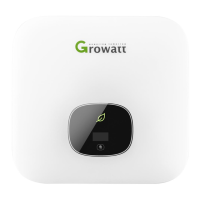
2.3 Installing the Monitor
2.2 Installing the Mounting Bracket And Min 2500-6000 TL-XH
Install
Remove
Ensure that the Monitor is installed securely.
Fix the wall bracket
Installation & Tighten
screw assemblies
The Inverter
Side
The Inverter
Side
The Inverter
Side
The Inverter
Side
Notice:
Before installing the device,check that the pack-
age contents are intact and complete against
the packing list.If any damage is found or any c-
omponent is missing,contact your dealer.
Overview
2.
2.1 Installation Requirements
Tilt and Space
Drilling holes
1.
3.
Connect the AC output power cable to the AC connector.
The Inverter
Side
Lock the housing
Object
Description
Quantity
A
B
C
D
E
F
G
1
1
1
1
2
3
1
Inverter
Mounting bracket
Quick Guide
Monitor(Optional)
Signal connector
Self-tapping screws
Safety-lock screw
Plastic expansion pipe
PV+/PV- terminal
PV+/PV- and BAT+/BAT- metal terminal
AC connector
Uninstall signal or AC connector tool
Uninstall PV or BAT terminal tool
H
J
L
I
K
M
3
2/2
3/3
1
1
1
3.2 Installing the BAT Input Power Cable
Positive metal
terminal
Positive metal
terminal
Positive connector
Positive connector
Negative metal
termina
Negative metal
termina
The Inverter Side
The Inverter Side
Pull the BAT input power cable back to ensure that it is connected securely.
The Inverter Side
The Inverter Side
Negative connector
Negative connector
3.3 Installing the AC Output Power Cable
The Inverter
side
The Inverter
side
SYS COM Port Pin Definitions
NO
Definition
3.4 Installing the SYS COM Signal Cable
1
2
3
4
5
6
7
8
Enable-: Connect BDC enable signal
port negative
Enable+: Connect BDC enable signal
port positive
RS485A2:Connect Min ShineBus or Third
party monitoring equipment
RS485B2:Connect Min ShineBus or Third
party monitoring equipment
RS485A1:Signal for meter
RS485B1:Signal for meter
BAT-B: Connect BDC communication RS485B
or CANL
BAT-A: Connect BDC communication RS485A
or CANH
The Inverter
Side
Lock the housing
Suggest using 6mm2 cables Ensure the exposed core wire is totally inserted into the cable hole and connected securely.
Notice: On the right is the Australian special AC connector.
The Client Side
The Client Side
The Client Side
L---Line
N---Neutral
PE-Ground
L---Line
N---Neutral
PE-Ground
N
N
L
L
PE
PE
C
l
ic
k!
Cli
c
k!
Cl
ic
k!
Cables
Cables
4~6mm²
4~6mm²
Cables
Cables
4~6mm²
4~6mm²