Page 5/43
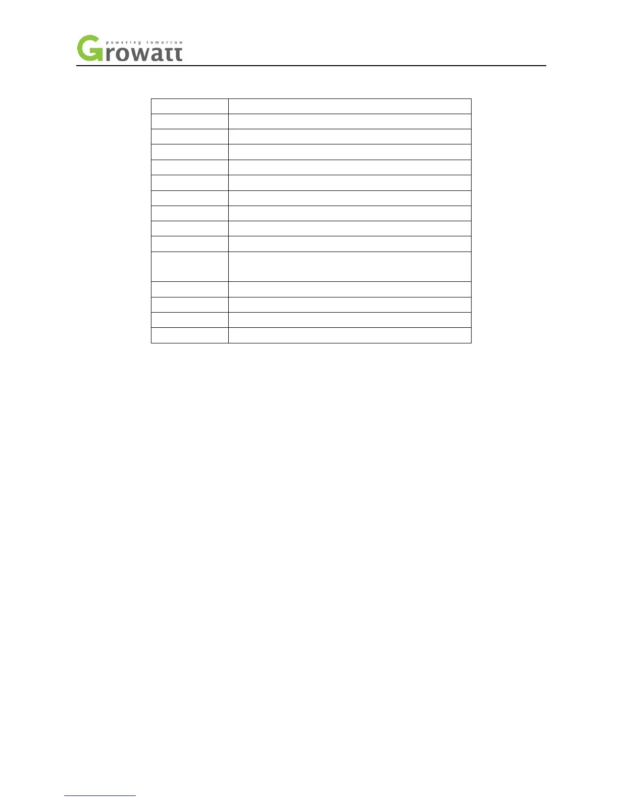
Position Description
A Tap on the marked area
B LCD display screen
C LED of status display
D DC output
E panel input
F DC switch
G Touch ground point of box
H AC socket
I The reserved antenna hole
J Lead battery temperature test line and current transformer
measurement line connector
K LAN connector
L RS232 cover board
M battery power connecting pin
N lithium BMS RS485 connector
1.1 Safety Instructions
1. Pease read this manual carefully before the installation, The company has the right not to quality assurance, If
not according to the instructions of this manual for installation and cause equipment damage.
2. All the operation and connection please professional electrical or mechanical engineer.
3. During installation, Please don’t touch the other parts within the box
4. All the electrical installation must comply with the local electrical safety standards
1.4 Safety Instructions
1)Pease read this manual carefully before the installation, The company has the right not to quality assurance, If
not according to the instructions of this manual for installation and cause equipment damage.
2)All the operation and connection please professional electrical or mechanical engineer.
3)During installation, Please don’t touch the other parts within the box
4)All the electrical installation must comply with the local electrical safety standards
5)If equipments needs to maintain, Please contact with local specify system installation and maintenance
personnel
6)Use the equipment to combined to grid needs to obtain the permission of local power supply department
7)When install PV modules in the daytime, Installer should cover the PV modules by opaque materials, Otherwise
it will be dangerous as high terminal voltage of modules in the sunshine
2 Safety
2.1 Purpose Use
The system chart of PV energy storage: