MACHINE SET-UP
CONNECT AIR SUPPLY
GraverSmith recommends 1.4 CFM (40 liters/min.) at a
minimum 45 psi (3.1 bar). Maximum input is 125 psi (8.6 bar). We
encourage reducing the air pressure from the compressor with
a regulator to 45~60psi (3.1~4.1 bar) as this ensures a stable
air pressure supply. The compressed air must be clean, dry, and
oil-free. The lter supplied with each unit is a nal lter and is not
capable of removing large amounts of water, oil, or contaminants.
If the air supply has excessive water, oil, or contaminants, an
additional lter/water trap/coalescing lter should be installed
ahead of the unit. Be sure to clean/purge all lters and water
traps regularly. IMPORTANT: Never add oil to the compressed
air for the GraverSmith. Oil can foul internal parts and cause
erratic handpiece operation. If your compressor requires oil,
YOU MUST use Coalescing Filter (#004-579) to ensure this oil
does not contaminate your compressed air.
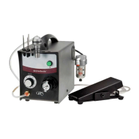
Decide where you want to locate
the machine on your bench. NOTE:
The machine must be in vertical
position - DO NOT lay on its side.
Next, decide where you would like
the air lter located. Make its location
readily accessible so it is easy to purge
moisture from the bowl. You may attach
the air lter to your machine, bench, or
wherever you desire. Keep the location
of the lter where you can see it and
easily maintain it. Here we show it
attached to the back right side of the machine (FIG. 2).
CONNECTING THE HOSES
If “push-to-connect” ttings are new to you, they are amazing. With
the AIR PRESSURE SHUT OFF, simply insert the hose all the way
into the tting opening –– it stays attached. To disconnect, press in
on the orange ring while gently pulling the hose out.
Locate the air input tting on the air lter. It is identied on the
air lter with the marking “N
”. Connect your 1/4" OD (6,35mm)
air supply hose directly to the “push-to-connect” tting simply by
pushing the hose end inside the orange ring receiver (A). If your
air supply hose is larger than 1/4" OD you have two options. Use
a reducer, not supplied, and step the air hose size down to a 1/4"
OD (6,35mm), or replace the “push-to-connect” tting with the
included barbed tting and attach air supply hose.
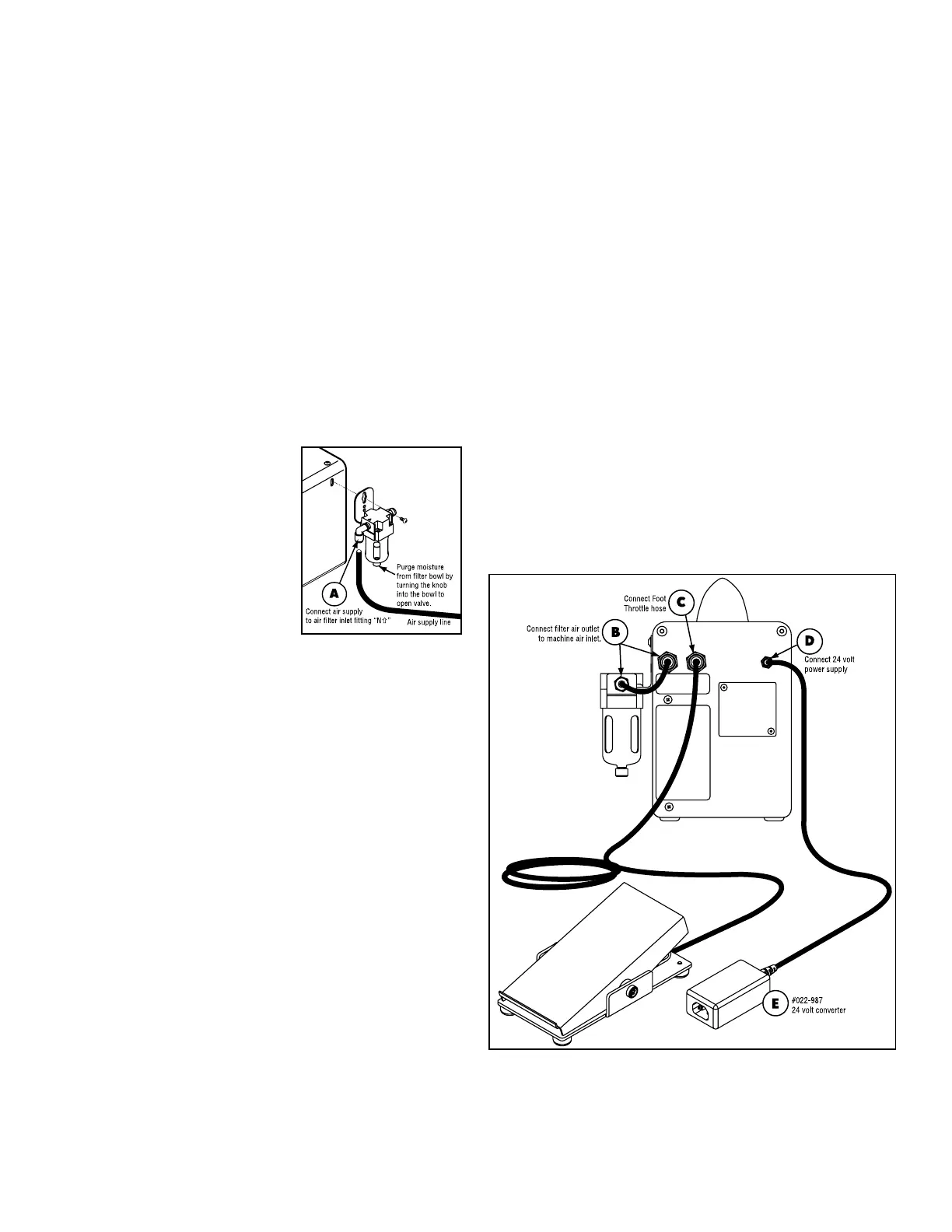
Locate the 6' (1.82m) air hose (#044-069) and cut a 5 1/2"
(139mm) piece from it. NOTE: This is if you are going to locate the
Air Filter as described above. Connect this 5 1/2" hose to the air
outlet (FIG. 3-B) on the air lter, opposite the air input. Connect
the other end of that hose into the tting on the back of the
machine (FIG. 3-B) marked AIR INPUT on the label below it. Use
these same connections no matter where you locate the lter.
CONNECT FOOT THROTTLE
Place the foot throttle on the oor in a convenient position. Run
the hose to the back of the machine. If you need to “snake” the
hose through an opening on your bench, make sure the hose is
not pinched or kinked. Connect the hose from the foot throttle to
the “push-to-connect” tting above the label marked THROTTLE
CONNECTION (FIG. 3-C).
CONNECT ELECTRICAL POWER
IMPORTANT: The ROTARY VALVE is lubricated by air
passing through it. DO NOT RUN THE MACHINE UNLESS
AIR SYSTEM IS ON.
Connect the electrical power cord into the 24 Volt Converter Box
(FIG. 3-E). Plug the converter cord into the jack on the back of
the machine (FIG. 3-D). IMPORTANT NOTE: DO NOT USE
OTHER BRANDS OF 24 Volt Converters - DAMAGE WILL
OCCUR to the machine.
The power converter supplied with your machine will accept 120
Volt or 230 Volt. All that is necessary to convert power supply is
to use the 230 Volt adapter supplied in the accessory box. You
are ready to tune the handpiece.
FIG. 3
FIG. 2
 Loading...