English (GB)
35
14. External PWM control mode and signals
PWM can only operate if you have set the pump to PWM mode.
See section 13.4 Operating and alarm status.
PWM profile C input signal (solar)
At low PWM signal percentages (duty cycles), a hysteresis
prevents the circulator from starting and stopping if the input
signal fluctuates around the shifting point. Without PWM signal
percentages, the circulator will stop for safety reasons. If a signal
is missing, for example due to a cable breakage, the circulator
will stop to avoid overheating of the solar thermal system.
Fig. 48 PWM input profile C
Digital low-voltage PWM signal
The square-wave PWM signal is designed for a 100 to 4,000 Hz
frequency range. The PWM signal is used to select the speed
(speed command) and as feedback signal. The PWM frequency
on the feedback signal is fixed at 75 Hz in the circulator.
Duty cycle
d % = 100 x t/T
Example
Fig. 49 PWM signal
15. Digital signal converter
To replace UPS SOLAR with a new ALPHA SOLAR pump which
fulfils the ErP requirements, we offer two solutions:
• Exchange the existing SOLAR controller to a controller
suitable for high-efficiency pumps.
• Keep the old controller, and use the phase control. Use a
signal converter, SIKON HE, which can convert the existing
phase control to a PWM signal for the ALPHA SOLAR.
When you use SIKON HE, you can replace the conventional 230
V UPS SOLAR pump with a Grundfos ALPHA SOLAR pump
without having to change the controller. The function of the
performance control of the pump is maintained.
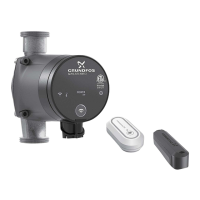
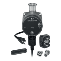
Fig. 50 Digital signal converter (SIKON HE)
For further information about the controller, see www.prozeda.de.
16. Technical data
TM05 1575 3211
PWM input signal
[%]
Pump status
≤ 5 Standby mode: off
> 5 / ≤ 8 Hysteresis area: on/off.
> 8 / ≤ 15 Minimum speed: IN
> 15/90 Variable speed: min. to max.
> 90 / ≤ 100 Maximum speed: max.
Example Rating
T = 2 ms (500 Hz) U
iH
= 4-24 V
t = 0.6 ms U
iL
≤ 1 V
d % = 100 x 0.6 / 2 = 30 % I
iH
≤ 10 mA (depending on U
iH
)
TM04 9911 0211
Abbreviation Description
T Period of time [sec.]
d Duty cycle [t/T]
U
iH
High-level input voltage
U
iL
Low-level input voltage
I
iH
High-level input current
Max.
PWM input signal [%]
Speed
TM06 5809 0216
System pressure Maximum 1.0 MPa (10 bar)
Minimum inlet pressure
0.05 MPa (0.50 bar) at a liquid
temperature of 95 °C
Maximum liquid
temperature
2-110 °C at an ambient temperature
of 70 °C
2-130 °C at an ambient temperature
of 60 °C
Enclosure class IPX4D
Motor protection No external protection needed
Approvals and
markings
VDE, CE
Water-propylene glycol
mixture
Maximum water-propylene glycol
mixture is 50 %.
Note: The water-propylene glycol
mixture reduces the performance due
to higher viscosity.

 Loading...

