5
English (US)
7.1.3 Additional protection
If the CU331SP is connected to an electrical installation where an
earth leakage circuit breaker (ELCB) is used as additional
protection, the circuit breaker must be of a type marked with the
following symbols:
The circuit breaker is type B.
The total leakage current of all the electrical equipment in the
installation must be taken into account.
The leakage current of the CU331SP in normal operation can be
seen in section 15.7.1 Mains supply (L1, L2).
During start and in asymmetrical supply systems, the leakage
current can be higher than normal and may cause the ELCB to
trip.
7.1.4 Motor protection
The motor requires no external motor protection. The CU331SP
protects the motor against thermal overloading and blocking.
7.1.5 Protection against overcurrent
The CU331SP has an internal overcurrent protection for overload
protection on the motor output.
7.1.6 Protection against mains voltage transients
The CU331SP is protected against mains voltage transients
according to EN 61800-3, second environment.
7.2 Mains and motor connection
The supply voltage and frequency are marked on the CU331SP
nameplate. Make sure that the CU331SP is suitable for the power
supply of the installation site.
7.2.1 Mains switch
A mains switch can be installed before the CU331SP according to
local regulations. See fig. 5.
7.2.2 Wiring diagram
The wires in the terminal box must be as short as possible.
Excepted from this is the protective conductor which must be so
long that it is the last one to be disconnected in case the cable is
inadvertently pulled out of the cable entry.
Fig. 5 CU331SP wiring diagram
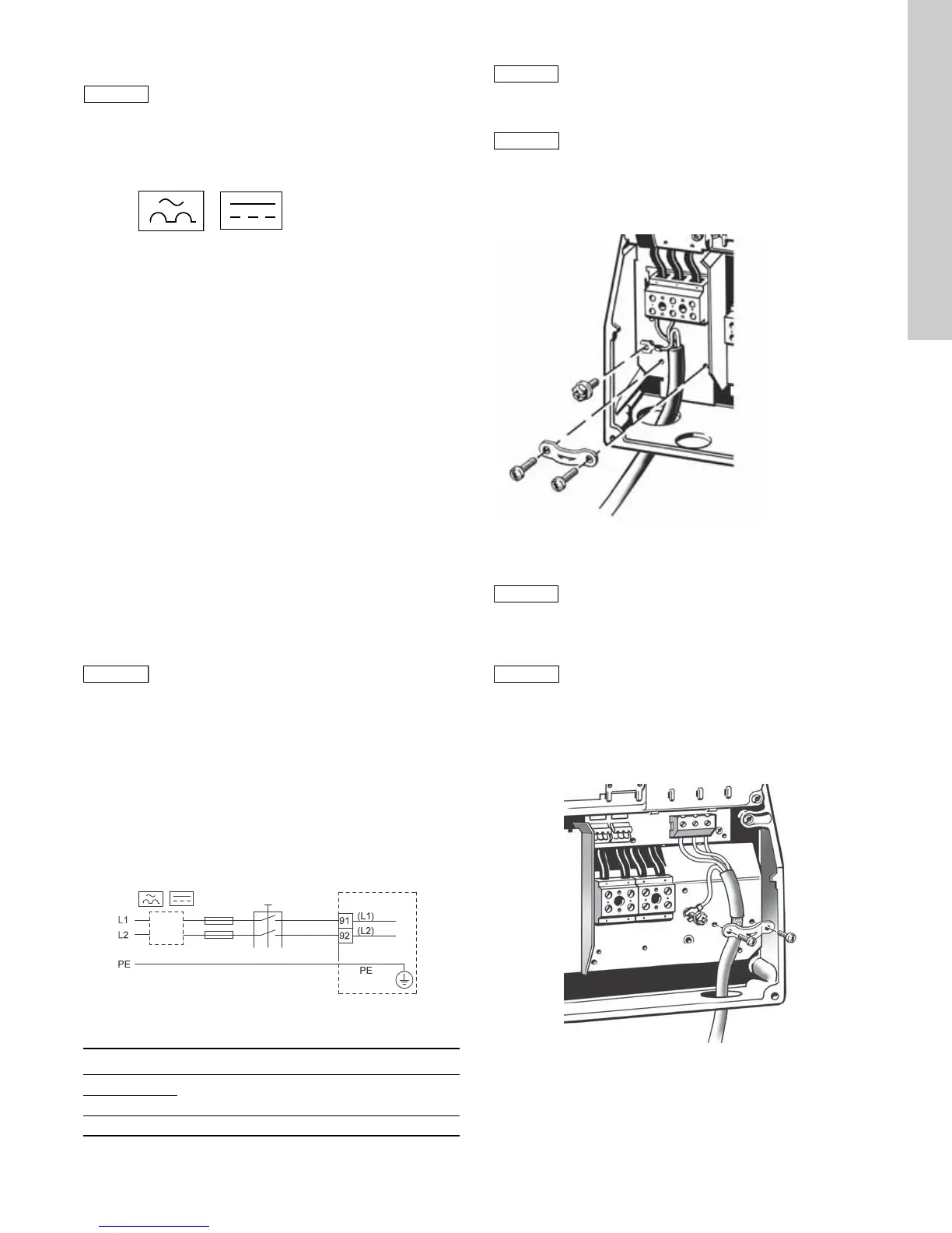
Mains connection
1. Connect the ground wire to terminal 95 (PE). See fig. 6.
2. Connect the power leads to the terminals 91 (L1), 92 (L2).
3. Fix the mains cable with a cable clamp.
Fig. 6 Mains connection
Motor connection
1. Connect the ground wire to terminal 99 (PE). See fig. 7.
2. Connect the motor leads to the terminals 96 (U), 97 (V), 98
(W).
3. Fix the screened cable with a cable clamp.
Fig. 7 Motor connection
The leakage current to ground exceeds 3.5 mA.
The maximum output voltage of the CU331SP is
equal to the input.
Example: if the supply voltage is rated at 208V
choose a 208V motor for operation.
TM05 5867 3912
Terminal Function
91 (L1)
Single-phase supply
92 (L2)
95/99 (PE) Ground connection
For single-phase connection, use L1 and L2.
Check that mains voltage and frequency
correspond to the values on the nameplate of the
CU331SP and the motor.
CU331SP drive is usable with 3-phase input
power by connecting leads to 91 (L1), 92 (L2), and
93 (L3).
The motor cable must be screened for the
CU331SP to meet EMC requirements.
TM03 9020 2807