7
English (US)
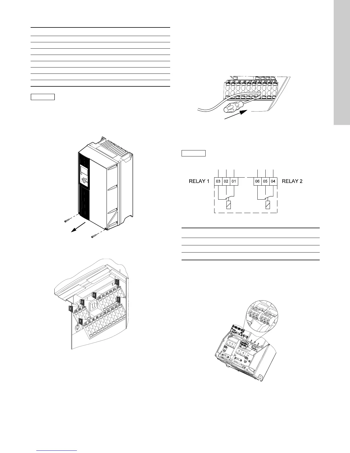
7.3.3 Terminal Key
7.3.4 Access to signal terminals
All signal terminals are behind the terminal cover of the CU331SP
front. Remove the terminal cover as shown in Fig.12.
Fig. 12 Access to signal terminals
Fig. 13 Signal terminals
7.3.5 Fitting the conductor
1. Remove the insulation at a length of 0.35 to 0.40 inches (9 to
10 mm).
2. Insert a screwdriver with a tip of maximum 0.015 X 0.1 in (0.4
X 2.5 mm) into the square hole.
3. Insert the conductor into the corresponding round hole.
Remove the screwdriver. The conductor is now fixed in the
terminal.
Fig. 14 Fitting the conductor into the signal terminal
7.4 Connecting the signal relays
Fig. 15 Terminals for signal relays (normal state, not activated)
7.4.1 Signal Relay
The signal relays on the CU331SP are predefined as follows:
Relay 1: Pump running
Relay 2: Alarm.
Fig. 16 Terminals for relay connection
Terminal Type Function
12 +24 V out Supply to sensor
18 DI 1 Digital input, start/stop
20 GND Common frame for digital inputs
55 GND Common frame for analog inputs
54 AI 2 Sensor input, sensor 1, 0/4-20 mA
61 RS-485 GND Y GENIbus, frame
68 RS-485 A GENIbus, signal A (+)
69 RS-485 B GENIbus, signal B (-)
The RS-485 screen must be connected to frame.
TM03 9004 2807
TM03 9025 2807
TM03 9026 2807
As a precaution, signal cables must be separated
from other groups by reinforced insulation in
their entire lengths.
TM03 8801 2507
Terminal Function
C 1C 2Common
NO 1 NO 2 Normally open contact
NC 1 NC 2 Normally closed contact
TM03 9008 2807