English (US)
8
7.5 EMC-correct installation
This section gives guidelines for good practice when installing the
CU331SP. Follow these guidelines to meet EN 61800-3, first
environment.
• Use only motor and signal cables with a braided metal screen
in applications without output filter.
• There are no special requirements to supply cables, apart
from local requirements.
• Leave the screen as close to the connecting terminals as
possible. See fig. 17.
• Avoid terminating the screen by twisting the ends. See fig.18
18. Use cable clamps or EMC screwed cable entries instead.
• Connect the screen to frame at both ends for both motor and
signal cables. If the controller has no cable clamps, connect
only the screen to the CU331SP.
• Avoid unscreened motor and signal cables in electrical
cabinets with variable frequency drives.
• Make the motor cable as short as possible in applications
without output filter to limit the noise level and minimise
leakage currents.
• Screws for frame connections must always be tightened
whether a cable is connected or not.
• Keep main cables, motor cables and signal cables separated
in the installation, if possible.
Other installation methods may give similar EMC results if the
above guidelines for good practice are followed.
7.6 RFI filters
To meet the EMC requirements, the CU331SP comes with the
following types of built-in radio frequency interference filter (RFI).
*Single-phase input - three-phase output.
Description of RFI filter types
RFI filter types are according to EN61800-3
Fig. 17 Example of stripped cable with screen
Fig. 18 Do not twist the screen ends
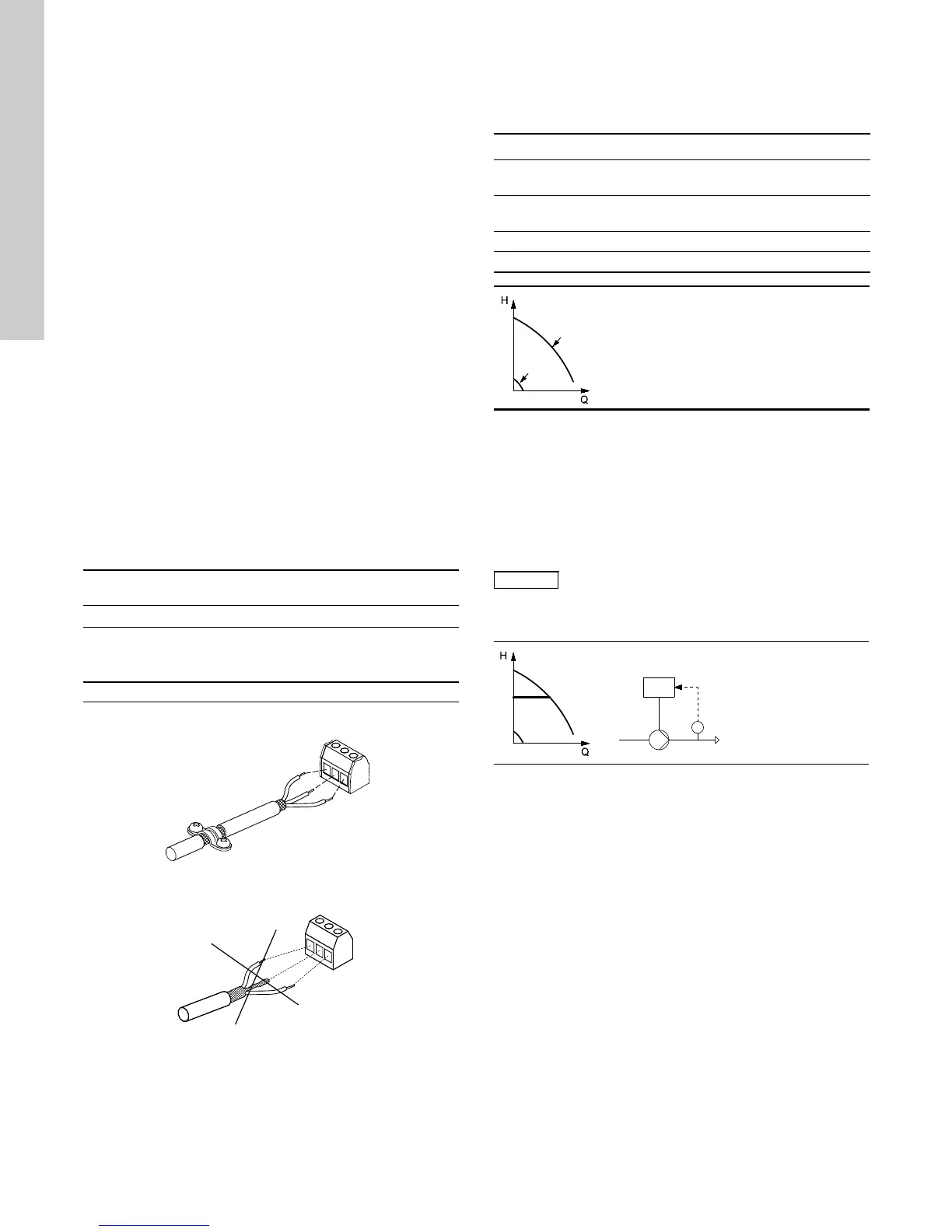
8. Operating modes
The following operating modes are set on the control panel in
menu OPERATION, display 1.2. See 11.5.2 Operating mode
(1.2).
Example: Max. curve operation can for instance be used in
connection with venting the pump during installation.
Example: Min. curve operation can for instance be used in
periods with a very small flow requirement.
9. Control mode
The control mode of the CU331SP is:
• Controlled operation (closed loop) with a sensor connected.
9.1 Controlled operation (closed loop)
Voltage Typical shaft power P2 RFI filter type
1 x 200-240 V * 1.5 - 10 hp C1
C1: For use in domestic areas.
TM02 1325 0901TM03 8812 2507
Operating mode Description
Normal
The pump is running in the control mode
selected
Stop
The pump has been stopped (green indicator
light is flashing)
Min. The pump is running at minimum speed
Max. The pump is running at maximum speed
TM03 8813 2507
Min. and max. curves.
The pump speed is kept at a given
set value for minimum and maximum
speed, respectively.
This cannot be changed
TM03 8476 1607
TM03 8805 2507
Constant pressure.
The pressure is
kept constant,
independently of
the flow rate.