7. Assembling MS4000 model C
For further information, see the MS4000 service video.
1. Place the stator housing (1) horizontally in the jaws (C) and
tighten it.
2. Fit the O-ring (24) on the threaded side of the bearing pipe (5).
Note: Lubricate the O-ring before fitting.
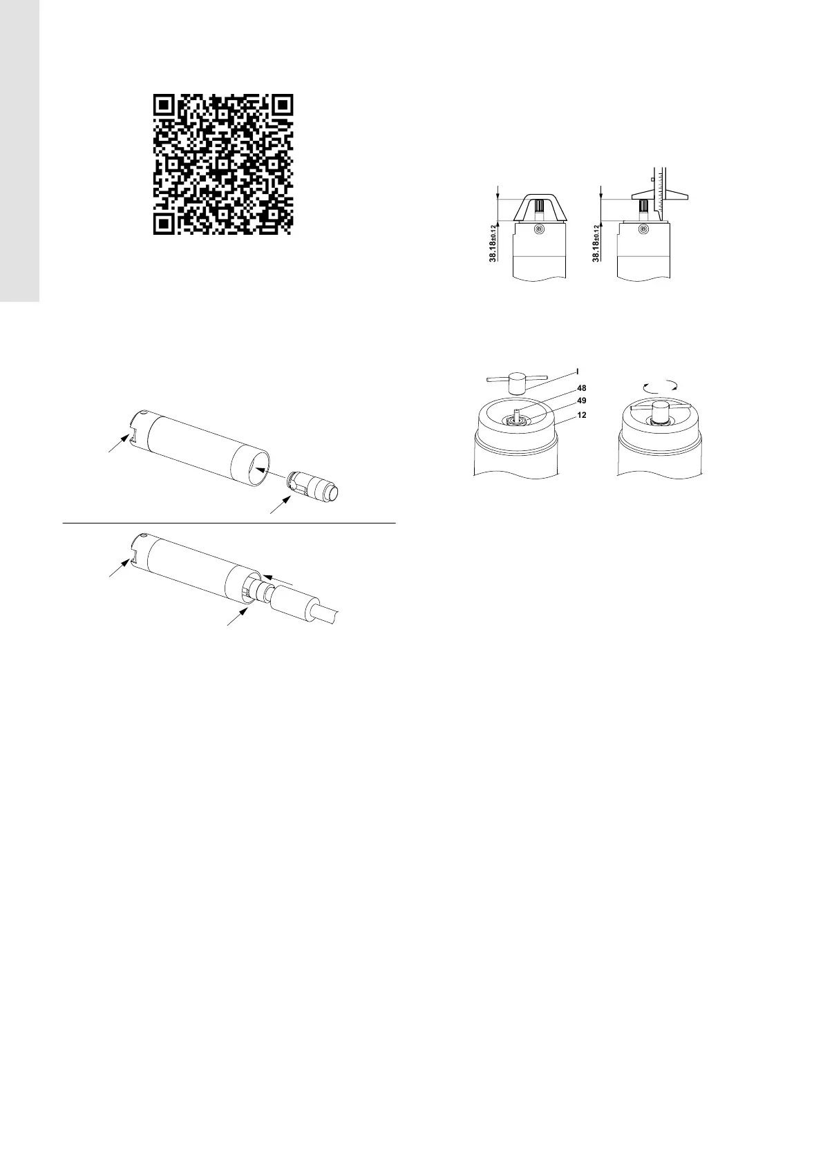
3. Align the plan surface of the bearing pipe (5) to the cable
connector of the stator housing (1) as shown on the drawings
below.
4. Insert the bearing pipe (5) into the stator housing and push it in
place using the specific assembly guide for the bearing pipe (H).
TM088292TM088293
5. Before installing the rotor assembly into the stator housing, the
radial bearing (4) and the rotating thrust bearing (6) should be
installed on the shaft with rotor (2).
6. First, fit the radial bearing (4) on the shaft with rotor (2).
7. Then, fit the rotating thrust bearing (6) onto the end of the shaft
with rotor (2).
8. Use a plastic mallet (T) and the punch for thrust bearing (G) to
fix the rotating part on the conus of the shaft.
Note: The rotating part must be put into the correct position
with one hit, otherwise, the shaft height may change over time
resulting in damage to the thrust bearing.
9. Fit this rotor assembly into the stator housing (1).
10. Insert the clamping ring (8).
11. Fit the stationary part of the thrust bearing (3) into the clamping
ring (8).
Note: Make sure that the clamping ring (8) is aligned with the
rotational stop features of the stationary thrust bearing (3).
12. Fit the bearing retainer (7) then fasten it using the key for the
bearing retainer (D). See section 3. Tightening torques and
lubricants.
13. Turn the motor to vertical position with the NDE facing upwards.
14. Place the adjusting screw (48) in the hole in the center of the
diaphragm (12), then screw the nut for the rubber diaphragm
(49) onto it using a 21 mm (3/4") open-end spanner (J). See
section Tightening torques and lubricants.
15. Fit the rubber diaphragm (12) on the top of the bearing retainer
(7) and fasten it using the special key for adjustment screw
(I). See section Tightening torques and lubricants.
16. Turn the stator housing 180° in the jaws, so the DE is facing
upwards.
17. Check the shaft height using a depth gauge (S), or a shaft
height gauge (B). The shaft height must be within 38.18 ±
0.12 mm. See the figure below.
Note: Make sure that the depth gauge is square between the
shaft end and the motor flange.
TM088382
18. Adjust the shaft height if necessary.
19. To adjust the shaft height, attend to the NDE of the motor
and adjust the height by turning the adjusting screw (48)
using the special key for the adjustment screw (I).
TM088431
20. Turn the stator housing 180° in the jaws, so the DE is facing
upwards.
21. Check the shaft height. See the details in step 17.
22. Turn the stator housing 180° in the jaws so the NDE is facing
upwards.
23. Fit the bottom cover (13) onto the mounted rubber diaphragm
(12).
24. Fit the lock washer (47) onto the end of the adjusting screw (48).
25. Fasten the nut (46) using a 13 mm (1/2") open-end spanner
(J). See section Tightening torques and lubricants.
Note: Be careful not to turn the adjusting screw when tightening
the nut.
26. When the nut (46) is fastened, bend one side of the lock washer
(47) against one side of the nut (46) using a screwdriver.
27. Turn the stator housing 180° in the jaws, so the DE is facing
upwards.
28. Fit the rotating part of the shaft seal ring (34) onto the shaft and
press it down.
29. Lubricate the recess inside the shaft seal housing (32) and the
outer surface of the stationary part of the shaft seal (33). See
section Tightening torques and lubricants.
30. Fit the stationary part of the seal ring (33) onto the shaft and
slide it down on top of the rotating part of the shaft seal ring
(34).
31. Fit the supporting ring (32a) on top of the stationary part of the
shaft seal ring (33).
32. Fit the spring (32b) into the supporting ring (32a).
33. Fit the shaft seal housing (32) over the supporting ring (32a)
on the top of the motor and tighten it by using the shaft-seal
housing tool (E). See section Tightening torques and lubricants.
34. Fit the sand shield (27) on the shaft and push it down to the
shaft seal housing (32).
35. Fit the supporting ring (35a) and the spline protector (35) on the
shaft and push them down to the sand shield (27).
16
English (GB)
 Loading...