GRUNDFOS INSTRUCTIONS
6
5.2 Twin System Pressurisation Unit (PHT A-T models).
A variation of the design allows a single pressurisation unit to provide top-up for two systems,
referred to as a Twin System Pressurisation Unit.
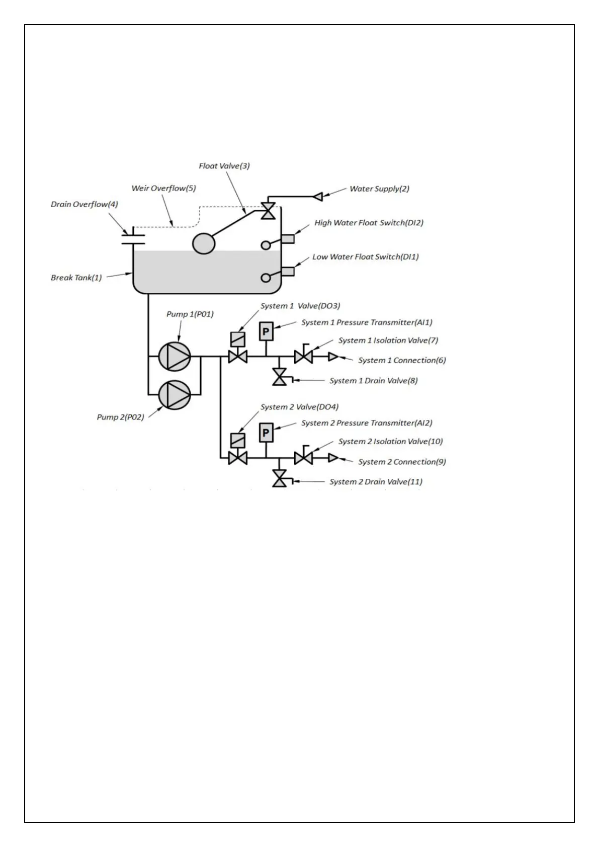
The following schematic shows the arrangement of a twin system pressurisation unit:
Fig. 3 – PHT A-T Schematic
This design allows the pressurisation unit to provide top up to two systems independently, with
different parameters, using the same two pumps.
In addition to the features described for a standard pressurisation unit, the following additional
features are provided:
The pressurisation unit is connected into the second system (System 2) through the System 2
Connection (9) via the System 2 Isolation Valve (10), a manual valve provided for isolating the unit
from the system. The System 2 Drain Valve (11) is provided for draining down the unit and/or
system and for commissioning purposes.
The System 2 Pressure Transmitter(AI2) measures the pressure in System 2.
The System 1 Valve (DO3) directs flow from the pumps into System 1.
The System 2 Valve (DO4) directs flow from the pumps into System 2.
When used in twin system mode the Programmable Output 3 (DO8) is set to function as a
critical fault output for System 2 by default and cannot be changed.
 Loading...