Do you have a question about the Grundfos PHT A N and is the answer not in the manual?
Provides information on the manual's content and scope for PHT A products.
Explains the meaning of symbols and warnings used in the document.
Defines the applicability of these installation and operating instructions to PHT A products.
Details the information found on the PHT A unit's silver label.
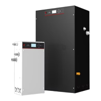
Explains the function of the PHT A pressurisation equipment in maintaining system pressure.
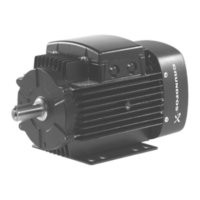
Describes the schematic and components of the standard PHT A unit.
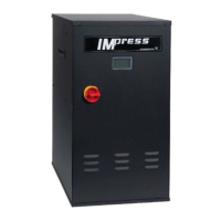
Explains the design for providing top-up to two systems independently.
Details the unit designed to deliver a mix of water and glycol into a single system.
Guidelines for unit delivery, inspection, warranty, and site storage.
Details on environmental conditions, installation location, and general requirements.
Lists operating conditions, electrical loads, and wall fixing dimensions.
Lists gross and net weights for various PHT A models.
Describes controller components, basic programming, and start-up sequence.
Explains main operating screens, fault indication, and menu system navigation.
Explains accessing menus, navigating, editing values, and exiting the system.
Details the function tree, fault indication, logging, and uploading procedures.
Explains how faults are displayed, navigated, logged, and acknowledged.
Explains digital outputs, interlock, general fault, and programmable outputs.
General safety precautions and requirements for installation.
Procedures for pump priming and float valve adjustment for different models.
Covers glycol settings for the V model and pump priming procedures.
A step-by-step checklist for performing the installation of the PHT A unit.
A checklist to ensure all commissioning steps are completed correctly before operation.
A form for recording all parameters and settings during unit commissioning.
Recommends planned preventative maintenance and annual servicing by qualified personnel.
Provides a diagram showing the connections for all PHT models.
Illustrates the detailed wiring connections for the PHT models.
Lists available spare parts with their part numbers and included items.
Covers procedures for taking the unit out of service.
Details safe dismantling and proper disposal procedures for the unit.
Lists common fault messages, their conditions, and recommended remedies.
Describes optional CIM modules for BACnet or Modbus communication.
Outlines the step-by-step procedure for fitting the CIM card to the main board.
Guides on clearing excess consumption warnings and flood protection faults.
Guides on checking system settings and manually operating pumps.
Guides for clearing fault/settings logs and resetting service reminders.
A section for recording history log entries and general notes.
| Series | PHT |
|---|---|
| Material | Cast Iron |
| Category | Industrial |
| Pressure Rating | PN10 |
| Connection Type | Flanged |