GRUNDFOS INSTRUCTIONS
23
8.1 PHT A-N/D/V unit – Float valve adjustment.
The PHT A-N unit must be fitted with a filter and depending on the site mains water
pressure a flow restrictor. This filter and flow restrictor are inserted into the mains
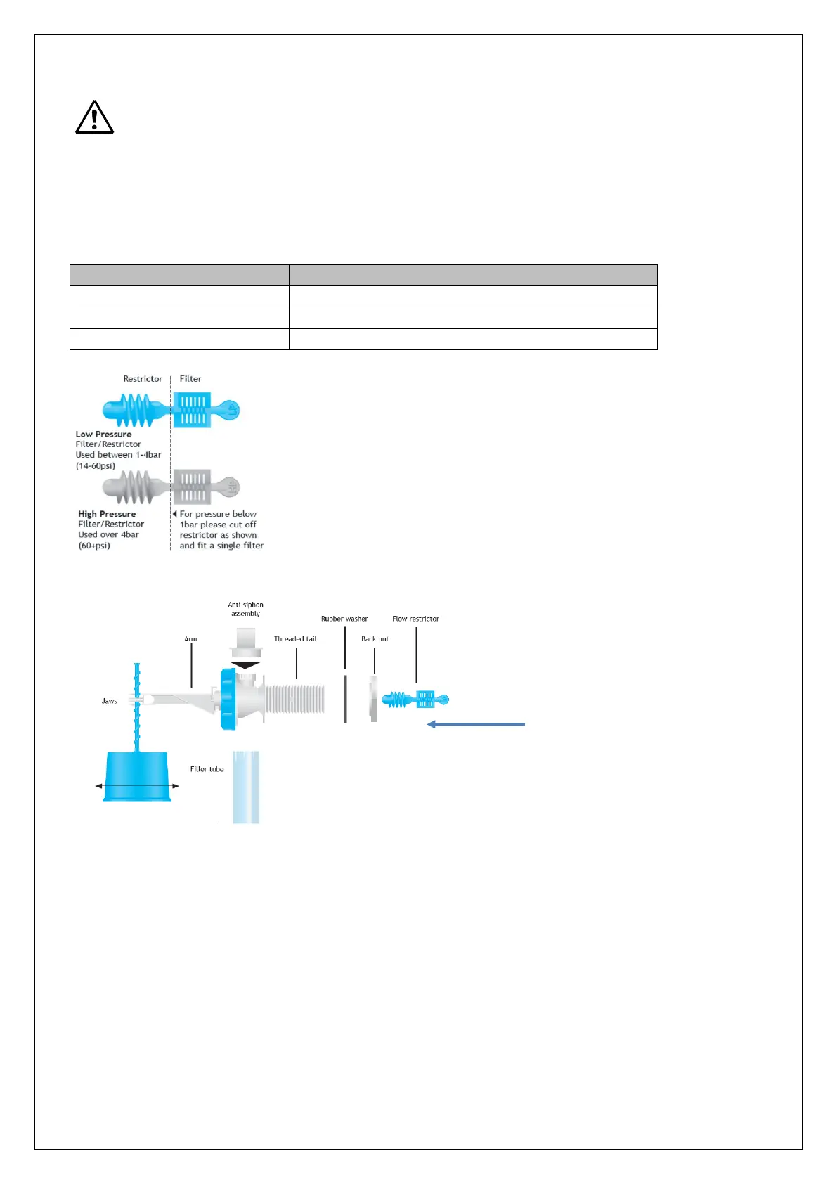
water fill valve, filter section first as shown below.
Failure to do so may result in damage to the PHT A-N unit
Two different flow restrictors are supplied, to be used as per the table below:
Filter and Low Pressure Restrictor (Blue)
Filter and High Pressure Restrictor (White)
Fig. 8 PHT A-N/D/V – Float valve filter and flow restrictor
Fig. 9 PHT A-N/D/V – Float valve filter and flow restrictor and level adjustment
Adjusting the water shut off level.
• Insert the float spiral stem horizontally between the two lower jaws and twist to engage upper jaw.
• Turn on the water supply.
• Allow the break tank to fill.
• Adjust water fill level, twisting float up or down until the water shut off level is just below the
Overflow.
Direction of filter
insertion
 Loading...