GRUNDFOS INSTRUCTIONS
5
5.1 Standard Pressurisation Unit (PHT A-N/D/F models).
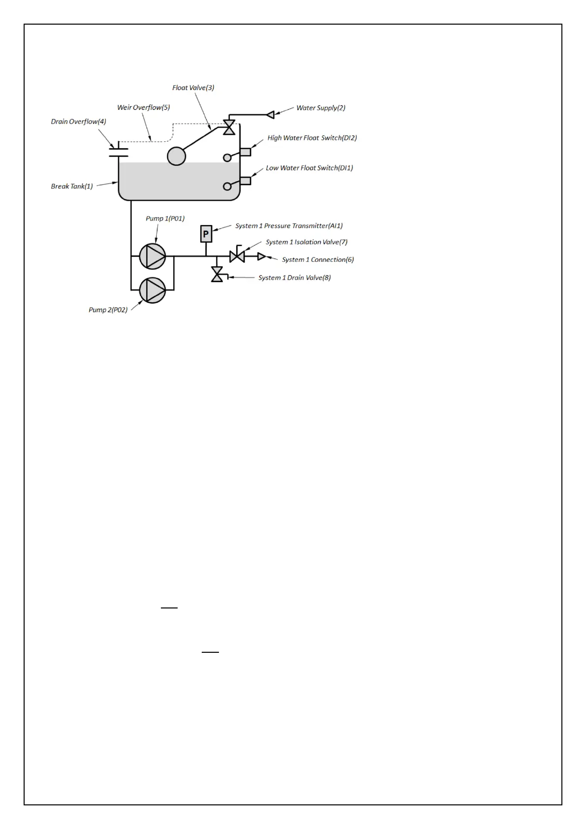
The following schematic shows the arrangement of the PHT A-N/D/F pressurisation models:
Fig. 2 – PHT A-N/D/F Schematic
The pressurisation unit is connected into the sealed system (System 1) through the System 1
Connection (6). The System 1 Isolation Valve (7) provides a point to isolate the unit from the
system. The System 1 Drain Valve (8) provides a point to drain down the unit and/or system and for
commissioning purposes.
The System 1 Pressure Transmitter (AI1) measures the pressure in System 1.
The PHT A unit can be configured with one or two pumps (P01 and P02) which when energised, will
transfer water from the Break Tank into System 1 to increase the pressure as required.
The pumps run in a duty/standby configuration where only one pump runs at a time (the duty
pump). The duty pump will always be the pump with the least accumulated total run time. This is a
measure to spread the wear evenly between the two pumps.
In single pump units Pump 1 (P01) permanently acts as the duty pump.
A Current Sensor (AI5) (not shown on schematic), measures the electrical current consumption of
Pump 1 (P01) and Pump 2 (P02) to detect faults in the pumps.
A System 1 Fault Output (DO1) (not shown on schematic) is used to interlock the boiler or chiller on
System 1 to disable it if the system pressure falls outside of safe operating limits. The fault name is
shown under the status bar on the Controller screen.
A General Fault Output (DO2) is provided to signal any fault presented by the unit.
Three additional outputs are provided which can be customised to signal a range of specific faults
or functions, Programmable Output 1 (DO6), Programmable Output 2 (DO7) and Programmable
Output 3 (D08).
The pressurisation unit is fitted
with a Break Tank (1) which is filled
from the Water Supply(2), via a
Float Valve(3). The break tank is
fitted with a Drain Overflow (4) in
case the Break Tank overfills, and a
Weir Overflow (5) in case the Drain
Overflow becomes blocked.
A Low Water Float Switch (DI1) is
fitted to detect a low water
condition.
A High Water Float Switch (DI2)
(optional extra) is fitted to detect
overfilling of the tank.
 Loading...