7
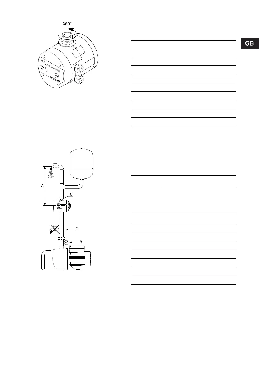
Fig. 1 Rotary outlet connection
3.1 Location
The installation location must be clean and well
ventilated.
The PM 2 must be positioned so that it is protected
from rain and direct sunlight.
The PM 2 can be installed in systems with or without
a pressure tank. See fig. 2.
Fig. 2 Installation example
The unit can be fitted directly to the pump discharge
port or between the pump and the first tapping point.
Pos. A in fig. 2:
It is recommended to install the unit so that the
height between the unit and the highest tapping point
does not exceed the values in the table below.
* Default setting.
See section 7.1 Start/stop according to water
consumption.
Pos. B in fig. 2:
To achieve correct operation, the pump should at
least be able to provide the discharge pressures in
the table below.
Minimum discharge pressure
* Default setting.
See section 7.1 Start/stop according to water
consumption.
** See section 7.2 Start/stop with 1 bar differential
pressure.
TM03 9707 1508TM04 0336 1508
Start pressure set
[bar]
Maximum height
[m]
1.5* 11
2.0 16
2.5 21
3.0 26
3.5 31
4.0 36
4.5 41
5.0 46
Start
pressure set
Operating mode
Start/stop
according to
water
consumption*
Start/stop with
1 bar
differential
pressure**
[bar] [bar] [bar]
1.5* 1.9 2.9
2.0 2.4 3.4
2.5 2.9 3.9
3.0 3.4 4.4
3.5 3.9 4.9
4.0 4.4 5.4
4.5 4.9 5.9
5.0 5.4 6.4