I
irwinemilyAug 5, 2025
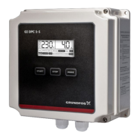
What to do if the Grundfos DPC 2-1 is flashing OVERLOAD?
- VVeronica ValdezAug 5, 2025
If the Grundfos Controller is flashing OVERLOAD, it indicates that the actual running amperage is higher than the calibrated or set running amperage, meaning the pump is in overload protection. The controller will attempt to restart the pump every 30 minutes until the running amperage returns to normal. You should also inspect the pump and motor winding.