Do you have a question about the Grundfos DID and is the answer not in the manual?
Identifies intended users and explains document/product symbols.
Ensures system safety during failure and outlines chemical handling precautions.
Covers product receipt, transport guidelines, and update policy.
Criteria for site selection, mounting, and hydraulic/sensor installation.
Ensures all connections are leak-free after installation.
Covers initial power-on, terminal wiring, and sensor connection to CU 382.
Details power connection, software initiation, and sensor initialization.
Guidelines for storage, handling, and the product's designed purpose.
Explains system operation and lists main components.
Information on identifying the specific DID model and its variants.
Lists standard DID configurations and hydraulic setups for sensors.
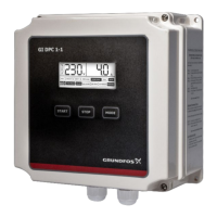
Identifies controls, display, and summarizes system features.
Describes main software screens like Status and Parameter.
Step-by-step guide for performing a quick calibration.
Accessing controller settings and general setup options.
Viewing and acknowledging system alarms.
Settings for sensors, managing parameters, and cleaning devices.
Adjusting measurement intervals and device date/time.
Configuring MODBUS and updating the control unit software.
Accessing parameter options and performing detailed calibration.
Step-by-step guides for different calibration types.
Viewing raw values and status of chosen parameters.
Configuring display, alarms, and parameter outputs.
Settings for PULSE/PWM outputs and parameter details.
Enabling and configuring pH compensation for chlorine sensors.
Accessing controller settings and defining setpoints.
Detailed settings for the Proportional-Integral-Derivative controller.
Configuration for 2-P controllers, disturbance control, and factors.
Setting controller direction, deadband, and stop behavior.
Mapping outputs and resetting controller states.
Defining how controllers react to alarms and errors.
Reviewing alarms and managing data via USB.
Details the format of data files saved to USB.
Routine cleaning for system components like strainers and units.
Periodic checks to ensure proper system operation and accuracy.
A comprehensive table listing common faults and their solutions.
Key hydraulic parameters for different DID variants.
Technical details for the control unit's 4-20 mA analog outputs.
Specifications for digital inputs, outputs, and relays.
Details on flow switch input and cleaning output functions.
Sensor connection details, housing, dimensions, and mains supply.
Environmental limits, certifications, and installation requirements.
Weight data and figures showing dimensions for mounting.
Figures detailing the physical dimensions of the control unit.
Dimensions for mounting the control unit on a wall.
Dimensions of the sensor with its holder.
Explains key symbols related to operation, safety, and warnings.
Statement of compliance with EU directives and standards for the product.
| Brand | Grundfos |
|---|---|
| Model | DID |
| Category | Controller |
| Language | English |