English (GB)
9
8. Control functions
8.1 Operating elements
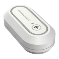
Fig. 6 Operating elements
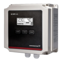
Fig. 7 Control unit CU 382
8.2 Functions overview
TM06 5854 0216
Pos. Description
1 Green power LED
2
Orange communication LED
• Flashes when there is a communication with a
sensor.
3
USB slot
• USB stick support for data export or software update.
4 Display
5
Operating buttons
[Back] button
– Leaves the current menu
[Up] button
– Moves one line upward (the selected
line has a triangle as first character)
– Increases values
[Function] button
– Enters the settings menus
– Disables / deletes values
[Left] button
– Moves left in views or values
[OK] button
– Enters the selected menu
– Confirms the selected line or value.
– Acknowledges alarms in the alarm
screen
[Right] button
– Moves right in views or values
[Down] button
– Moves one line downward (the
selected line has a triangle as first
character)
– Decreases values
TM06 5891 0216
Features CU 382-1 CU 382-3
1 plug for connection of digital s::can
sensors
●
3 plugs for connection of digital s::can
sensors
●
3 PID controllers
●●
2 digital (relay) outputs (adjustable as
controller and/or limit switch outputs)
●●
3 analog outputs (adjustable as
controller and/or measured value
output)
●●
1 alarm relay output
●●
1 cleaning valve output
●●
2 digital inputs (adjustable as remote
on/off, water meter pulse input or
setpoint switch)
●●
1 analog input (adjustable as flow meter
or external setpoint input)
●●
Data logger functionality (measured
values, logfile, configuration)
●●
USB host interface
●●
Multilingual user interface
●●
Modbus (over RS485)
●●
Flow switch input (from flow cell)
●●