Do you have a question about the Grundfos DPC 1-1 and is the answer not in the manual?
Essential safety precautions to prevent personal injury during operation.
Important warnings to prevent equipment damage or malfunction.
Manufacturer's disclaimer regarding liability for improper installation or use.
Details the diverse water and wastewater applications for the DPC controller.
Lists the key functionalities and capabilities of the DPC controller.
Outlines primary technical features like control characteristic and working modes.
Provides detailed specifications for voltage, current, trip times, and recovery times.
Lists the safety and protection features integrated into the controller.
Lists the necessary tools for controller installation and wiring.
Overview of the physical parts and elements of the controller.
Guidance on configuring the function switch for different applications.
Explanation of the display elements and icons on the LCD screen.
Details for connecting the main incoming and outgoing power supply.
Information on connecting probes or float switches to the controller.
Step-by-step guide to setting parameters and calibrating the unit.
Instructions to reset parameters to factory settings.
Guidance on installing liquid level probes for water level control.
Instructions for connecting and installing float switches.
Using probes or float switch for water supply and transfer.
Application for increasing water pressure using a pressure switch.
Using float switch for controlling drainage operations.
How to operate the pump manually using START/STOP buttons.
How the pump operates automatically based on sensor signals.
Explanation of how the controller responds to various fault conditions.
Method to reset the unit immediately without waiting for recovery time.
Recommended capacitor ratings based on motor power (kW).
Step-by-step guide for the proper installation of the running capacitor.
Common fault messages, their possible causes, and recommended solutions.
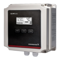
The Grundfos DPC 1-1 is a Digital Pump Controller designed for single-phase pumps, including monoblock and submersible types, with a capacity of up to 15 Amperes. This programmable device offers ease of use and comprehensive control for various water and wastewater applications.
The DPC 1-1 serves as a central control unit for pumps, enabling automated operation and protection. Its primary function is to manage pump activity based on liquid levels or pressure, ensuring efficient water transfer, tank filling, tank emptying, and pressure boosting in hydro-pneumatic systems. The controller is equipped with a range of protective features to safeguard the pump and ensure its longevity.
The DPC 1-1 is highly versatile and suitable for residential, industrial, and institutional settings where water and energy conservation are priorities.
Control Modes:
START and STOP keys, respectively. In this mode, the controller does not respond to signals from float switches or pressure switches.Application Versatility: The controller can be configured for different applications by adjusting DIP switch settings:
Sensor-Free Dry Run Protection: For submersible pumps in deep wells, the DPC 1-1 offers reliable and automatic protection against dry running even without external sensors. Users can achieve this by shorting terminals 1, 2, and 3.
Display and Alarms: The LCD screen provides real-time pump running information, including voltage, current, and operational status. It also displays fault conditions with visual and audio alarms, ensuring prompt awareness of any issues. Icons on the LCD indicate parameter configuration, time display (e.g., pump dry run trip time), and pump fault conditions.
The DPC 1-1 incorporates several features that simplify maintenance and enhance reliability.
Calibration:
The controller requires calibration to adapt to the connected pump's load. This process involves switching to manual mode, ensuring the pump is not running, then starting the pump to confirm its operation and current draw. A subsequent step involves pressing and holding the START key to initiate a countdown timer, after which the pump stops, and calibration is complete. This ensures the controller accurately monitors the pump's performance.
Erasing Parameters:
Whenever a pump is repaired or a new pump is installed, previous calibration parameters must be erased. This is done by switching to manual mode, ensuring the pump is not running, and then pressing and holding the STOP key. This action resets the unit to factory settings, indicated by a flashing "NO CALIBER" sign on the LCD, preparing it for re-calibration.
Protections and Automatic Recovery: The DPC 1-1 offers comprehensive protection mechanisms:
In case of a fault (dry run, overload, under/over voltage, etc.), the controller immediately stops the pump, displays the fault on the LCD, and automatically initiates a check for restarting conditions after a built-in time delay. The unit recovers automatically once abnormal conditions are cleared. Recovery times for dry run and overload can be adjusted, while under/over voltage recovery times are factory set. To immediately reset the controller without waiting for the recovery time, the power supply can be cut off and switched back on.
Memory Function: The controller retains its operational mode (Auto or Manual) and settings even after a power cut. When power is restored, the unit resumes operation in the same mode after a 10-second delay, ensuring continuous service.
Capacitor Installation: For Grundfos Submersible Pumps with PSC motors, a running capacitor is required. The manual provides specific capacitor ratings based on motor kW and detailed mounting instructions. This includes opening the cover, housing the capacitor in its holder, connecting cables to the specified terminals, and ensuring proper cable routing to avoid disturbing existing components. Adhering to these guidelines and using recommended capacitor types is crucial for warranty validity and optimal pump performance.
| Category | Controller |
|---|---|
| Brand | Grundfos |
| Protection Class | IP65 |
| Weight | 0.5 kg |
| Power Supply | 230 VAC, 50/60 Hz |
| Operating Temperature | 0-50 °C |
| Humidity | 95% RH non-condensing |