English (GB)
5
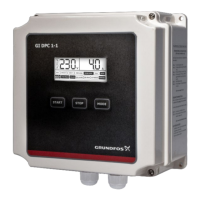
5.3 Connection of sensors to the control unit CU 382
All sensors for the DID will be delivered with a plug connection on
the sensor itself. The connection cable C-1-010 has to be used to
connect the sensor to a compatible socket provided on the control
unit CU 382. Sensors for submersed installation are equipped
with a fixed cable already including the plug.
Before connecting the sensor, ensure that the sensor plug and
the connector on the control unit are dry and clean. Otherwise
communication errors and / or device damage might occur.
Connectors not in use should always be covered with the
protective cap.
5.4 Connection of valves for automatic cleaning
Valves, used for steering of the automatic sensor cleaning in case
of submersed installation, can be wired to the terminals 10
(Valve) and 11 (GND) to supply the valve with 12 VDC power (see
Fig. 2). In case a separate cleaning signal is used, this can be
wired to the terminal 12 (Clean In). This steering signal has to be
at least 5 V.
5.5 Connection of further in/outputs
For connecting actuator devices (e.g. dosing pumps or chlorine
regulators), please observe the relevant documentation.
5.6 Connection of power supply
The control unit CU 382 has to be connected to the appropriate
power supply. The connection of power supply (AC), has, without
fail, to include an earthed conductor wire (PE - "potential earth")!
The power supply earth (PE) is to be made properly. Process
medium (e.g. waste water) must be connected to the same earth
ground with less than 0.5 Ohm.
The power supply has to be equipped with an earth leakage
circuit breaker.
5.7 Starting up of operating software
Once the control unit CU 382 has been connected to the power
supply, it will show the s::can logo for 5 seconds while starting-up.
If the CU 382 internal settings have been reset to default, the CU
382 will start with the selection of the language (see section
9.2.8 Select language).
Subsequently, reading and information display will be shown. The
most recent information obtained by the CU 382 will be displayed,
even when no sensor is connected.
When no communication to an installed sensor is possible, only
those menus are available that are not concerning a sensor’s
settings (see section 9.2 General set up / status). In this case the
error relay will be in "error" mode. In case of such an error, an
entry to that effect is made in the logbook (see section 9.6 USB
menu / Data transfer).
5.8 Sensor initialisation
For operating the control unit CU 382 with one or several sensors
it is necessary to install (initialise) every single sensor on the CU
382. This can be done using the software supported initialization
process. During this process one sensor has to be connected to
the CU 382 and all other sensors are disconnected. Doing so an
individual address will be allocated to every sensor. The
corresponding address will be stored on the respective sensor.
Section 9.2.2 Manage parameters will guide you through this
task.
6. Storing and handling the product
The temperature and humidity limits for device storage, which are
described in the section Technical data, are to be observed at all
times. The device shall not be exposed to strong impacts,
mechanical loads or vibrations. The device should be kept free of
corrosive or organic solvent vapours, nuclear radiation as well as
strong electromagnetic radiation.
Damage to the sensor caused by wrong storage will not be
covered by warranty (please refer to the sensor manual).
Observe the permissible ambient conditions! See section
12. Technical data
WARNING
Electric shock
• Switch off the power supply before installing!
Enclosure class IP65 is only guaranteed if the
terminal cover is correctly sealed, if the front
panel of the terminal enclosure is closed and the
appropriate cable glands or dummy caps fitted.
• This type of work must be carried out by
authorized persons only and after disconnecting
the power supply!