Do you have a question about the Grundfos DPC 1-3 and is the answer not in the manual?
Overview of the controller's diverse applications in water and wastewater management.
Highlights key functionalities of the digital pump controller, including protection and display features.
Details primary control characteristics like level or pressure control and working modes.
Lists crucial technical parameters such as rated voltage, current, and trip response times.
Encompasses all built-in protection features for the pump and controller.
Provides supplementary specifications like ambient temperature, degree of protection, and dimensions.
Lists essential tools required for the proper installation of the controller.
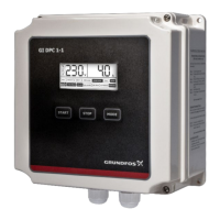
Identifies the main components of the controller unit for user familiarity.
Details the digital display screen of the controller and its information output.
Illustrates the connection points for incoming and outgoing power supply to the controller.
Shows the connection terminals for probes, float switches, and pressure switches.
Explains the process for calibrating the controller for optimal performance and protection.
Details the procedure for erasing previous parameters when a pump is repaired or replaced.
Guides on the correct installation of liquid level probes for control applications.
Provides instructions for installing float switches for liquid level detection.
Describes water supply and transfer applications using probes or float switches.
Indicates when the overhead tank liquid level reaches the upper probe, stopping the pump.
Signals when the borewell liquid level is below the pump intake, causing the pump to stop.
Indicates low liquid level in underground tank or well, stopping the pump.
Pump starts when pipeline pressure is below the set point and liquid level is adequate.
Pump stops when pipeline pressure reaches the set point.
Explains LCD messages for pressure boosting, including FULL, DRY RUN, and NO WATER.
Pump starts when float switch A reaches the up position.
Pump stops when float switch A reaches the down position.
Warns of overflow condition when float switch B is in the up position.
Explains LCD messages for drainage, including FULL, DRY RUN, NO WATER, and OVERFLOW.
Allows direct control of the pump using START and STOP keys, ignoring external signals.
Enables automatic pump operation based on signals from sensors, float switches, or pressure switches.
Details LCD messages for water supply/transfer applications, like FULL and DRY RUN.
Explains LCD messages for sewage/drainage applications, including FULL, DRY RUN, and NO WATER.
Describes LCD messages for pressure boosting applications, such as FULL.
Indicates low voltage; check power supply. Unit attempts restart after intervals.
Indicates high voltage; check power supply. Unit attempts restart after intervals.
Signals high current; check pump for jamming or motor issues. Unit attempts restart.
Indicates calibration was not completed; perform parameter calibration.
Indicates low liquid level; unit attempts restart after intervals or set time.
Signals current exceeding 200%; cut off power and repair/replace pump.
Indicates missing power phase; check power supply or repair cables.
The Grundfos DPC 1-3 is a Digital Pump Controller designed for three-phase pumps with a rated output power ranging from 1.5 to 16 Amperes. This device is an easy-to-use, programmable solution for controlling pumps in various water and wastewater applications. It is suitable for water transfer, tank filling, tank emptying, and pressure boosting in hydro-pneumatic systems, making it an ideal choice for residential, industrial, and institutional segments where water and energy conservation are crucial.
The DPC 1-3 serves as a comprehensive control and protection unit for pumps. It can operate in two main modes: Manual and Auto. In Manual mode, the user directly starts and stops the pump using the START and STOP keys. In Auto mode, the pump's operation is governed by signals from sensors, float switches, or pressure switches, depending on the application. The controller offers various control characteristics, including level control with probes for clear water or with floats, and pressure control with a pressure switch.
The DPC 1-3 boasts a range of features designed to enhance usability and pump protection:
The DPC 1-3 incorporates several protection features to ensure pump longevity and safe operation:
It is crucial to follow all safety instructions during installation and operation to prevent personal injury or damage to the equipment. Before any installation or maintenance, the controller must be disconnected from the power supply. The cover should not be opened while the pump is running, and no foreign objects should be inserted into the controller. All electrical connections must be performed by skilled and qualified personnel. AC power should never be connected to the output U,V,W terminals. The motor, controller, and power specifications must always match. The manufacturer is not liable for malfunctions resulting from incorrect installation, damage, modification, or operation outside the specified working range.
| Brand | Grundfos |
|---|---|
| Model | DPC 1-3 |
| Category | Controller |
| Language | English |