8 | Page 9 | Page
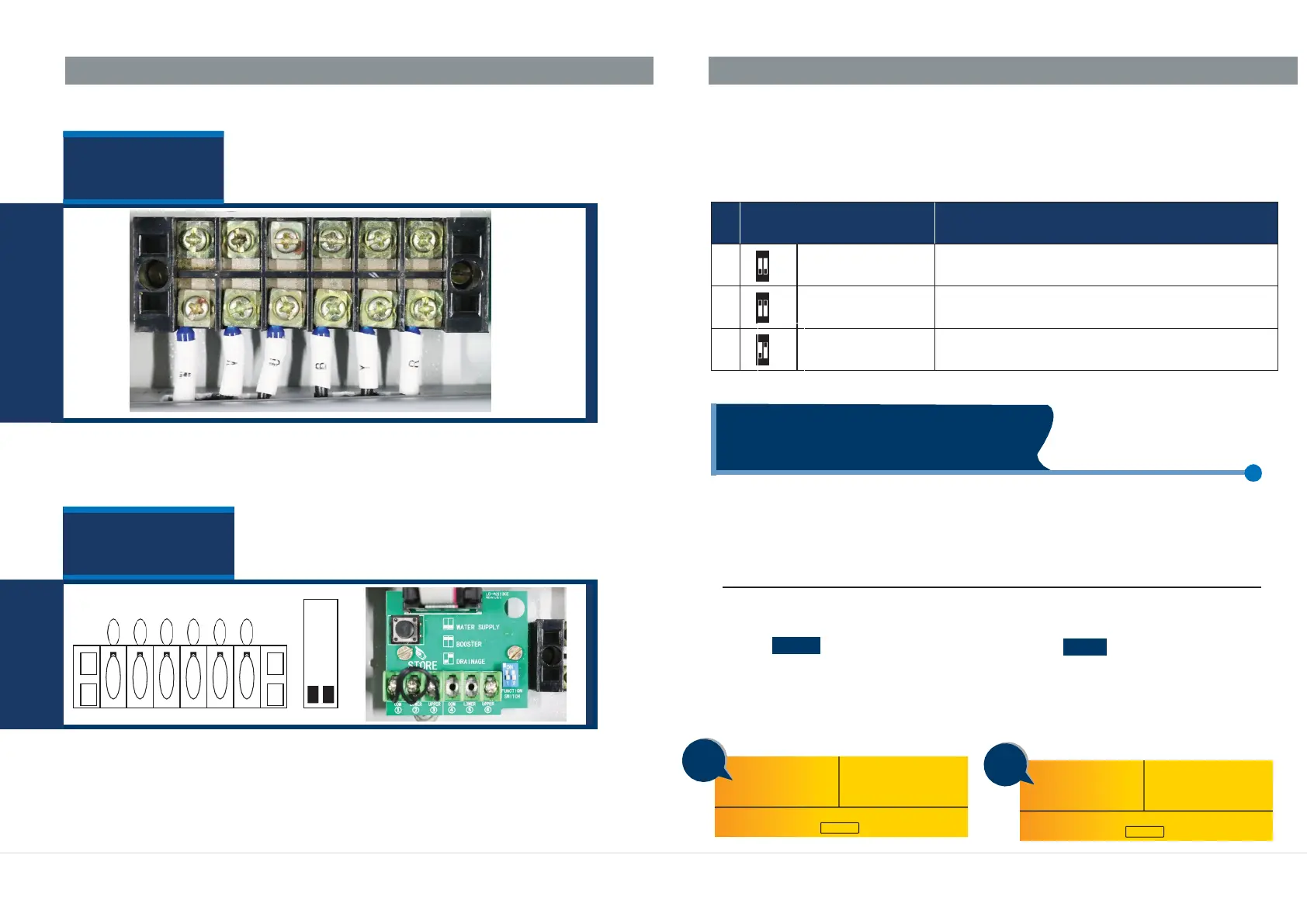
Control terminals
TERMINALS
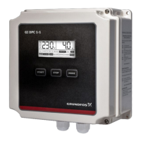
DIP SWITCH SETTINGS
Users can set the function switch to suit different applications. Before setting
the function switch; the unit should be disconnected from the power supply.
After completing the settings of dip switches, power may be applied to the unit.
Following signs will be displayed in voltage displaying area on the LCD
conforming to the following list.
(a) Power terminals for connecting mains incoming and outgoing
In order to achieve best performance of the controller and for providing
maximum protection to the pump, it is essential that parameter calibration is
done at the time of installation itself or after pump is repaired and installed back.
CALIBRATION:
Setting of parameters (calibration of unit according to the connected load):
X
X
X
X
X
X
(b) Control terminals for connecting probes or float switches
Press the MODE key to switch to manual
mode. Make sure the pump is not running
and LCD screen looks as below
Press the START key to run the pump,
confirm the pump is running OK and drawing
rated current. Also confirm the mains supply
is healthy and incoming voltage is normal,
LCD screen will display voltage and current
being drawn by pump:
A
A
Applied for drainage by liquid level control through
float switch
1
1
1
ON
1 2
3
Applied for water supply by pressure control through
pressure switch & pressure tank
222
ON
1 2
2
Applied for water supply by liquid level control through
probe/float switch
000
ON
1 2
1
ITEM
MESSAGES & IN
VOLTAGE DISPLAYING AREA
SWITCH
POSITION
ITEM
Power terminals
CALIBRATION AND ERASING