6 | Page 7 | Page
INSTALLATION
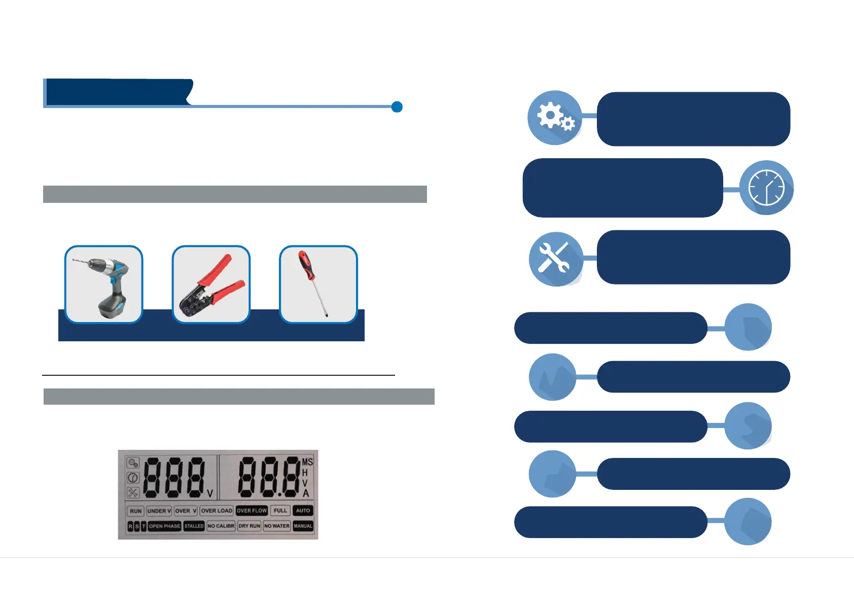
MEANING OF THE ICONS SHOWN ON THE LCD
Please read this manual carefully before starting installation and operation. Any
damage to the equipment caused due to failure to comply with the descriptions
in this manual in installation or operation will be beyond the scope of the
company’s quality guarantee.
TOOLS
USED
IN
CONTROLLER
INSTALLATION
Controller installation and wiring will need the following tools.
You also can choose the right tools according to your own experience.
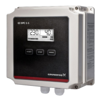
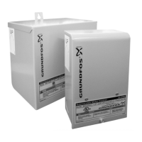
CONTROLLER COMPONENTS:
The parameter configuration icon,
when this icon appears, controller is in
manual parameter adjustment mode.
Time displaying icon, when this icon
appears, it means controller is
displaying some parameter of time,
eg: pump dry run trip time(units: seconds)
Pump fault icon, when this icon
appears, it means controller is
displaying some fault condition