English (GB)
5
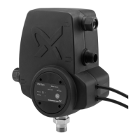
4.2 Mechanical installation
Install the unit on the discharge side of the pump.
The unit has a built-in non-return valve.
The unit can be connected directly to the pump
discharge port or between the pump and the first
tapping point.
4.3 Location
The unit must be positioned so that it is protected
from rain and direct sunlight.
The unit can be installed in systems with or without a
pressure tank.
Fig. 2 PM Rain and JP pump
Fig. 3 PM Rain and SB pump
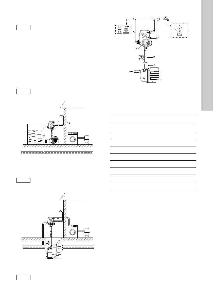
Fig. 4 Installation example
Pos. A in fig. 4:
We recommend you to install the unit so that the
height between the unit and the highest tapping point
does not exceed the values in the table below.
* Default setting.
See section 5.1 DIP switches.
Use a suitable thread seal tape on the
male and female threads of the
PM Rain.
A mounting bracket for wall mounting
can be ordered separately.
TM05 1517 2911
We recommend PM Rain and JP pump
for positively fed systems only, for
example above-ground collecting
tanks.
TM05 1518 3111
We recommend PM Rain and SB pump
for suction applications, for example
underground collecting tanks.
TM05 1534 3211
Start pressure set Maximum height
[bar] [kPa] [m]
2.5* 250 21
3.0 300 26
3.5 350 31
4.0 400 36
4.5 450 41
5.0 500 46
5.5 550 51
6.0 600 56
 Loading...