4
3. Installation
3.1 Important instructions
• An inlet head of at least 2 metres is recommended.
• Non-return valves
Do not fit non-return valves in the suction line to the pump.
Make sure that the pump can vent back to the supply tank.
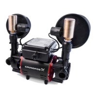
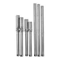
• STC, STR, SSR, STL and SSL pumps
The strainers supplied with the pump must be used on suction
connections. See fig. 1.
• Push-fit connections (SSN, SSP, STN and STP pumps)
The pump suction and discharge ports are fitted with push-fit
connections. The flexible hoses supplied with the pump must
be used.
Make sure that each hose connection is fully inserted to a
minimum depth of 33 mm.
• Disconnecting hose
To disconnect the "push-fit" hose, firmly push down the white
or grey retaining ring while pulling out the hose.
• Hot-water supply
The hot-water supply to the pump suction port should be
connected from the first outlet from the hot-water cylinder
expansion pipe, i.e. use a Surrey flange. An Essex flange is
recommended for STP 3.0 B, SSP 3.0 B, STP 4.0 B,
STN 3.0 B, SSN 3.0 B and STN 4.0 B pumps.
• No solder flux
Do not allow any solder flux to come into contact with any of
the plastic parts of the pump.
• Do not let the pump run dry
Purge with water thoroughly for 5 minutes before running the
pump.
• Test the system
Complete all pipework before making any electrical
connections. Do not allow any water to enter into the electrical
terminal box. After completing installation, the whole system
must be thoroughly tested, operating both hot and cold water
at maximum flow.
Maximum hot-water temperature setting must not exceed
60 °C (140 °F) in accordance with BS 6700: 2006.
Finally check that each connection is watertight and not
leaking.
3.2 Positioning the pump
Keep the pump as close as possible to the source of hot and cold
water.
For optimum performance, ensure the following:
• A good water flow to the pump.
• Sufficient head.
• Unrestrictive pipework, 22 mm is recommended.
• Provision to prevent air locks.
Place the pump in a well-ventilated location, e.g. on the floor of
the airing cupboard.
The pump must be mounted horizontally with the discharge ports
vertically upwards to ensure correct operation of the flow
switches.
To reduce noise, we recommend the pump be mounted on a
small concrete foundation of approximately 225 x 225 mm and
40-50 mm thick.
Connect the pump and shower system as shown in fig. 2.
To achieve 0.5 l/min. to turn the flow switches on, there must be
a minimum height between the cold-water storage tank and the
highest point of the pump outlet pipework of approximately
250 mm. See fig. 2.
The pump must be installed in accordance with the Water Supply
(Water Fittings) Regulations 1999.
For installation within a bathroom, locate the pump in accordance
with the IEE Wiring Regulations seventeenth edition
(BS 7671: 2008) Part 6, Section 601, for a shower pump with an
IPX2 enclosure. The pump must be positioned at least 0.6 metres
horizontally or 3 metres vertically away from any bath, shower
tray or basin.
3.2.1 Negative head
If the water level in the cold-water storage tank is below the level
of the shower outlet, this is called a negative-head system. To
enable the pump to operate, a negative-head pump must be
used. See section 2.1 Type key.
Do not connect the pump directly to the water
mains supply.
The pump cannot be used with combination
boilers.
Make sure that no foreign particles (such as
solder and dust) are allowed to enter the pump.
The pump cannot operate if the level of the water
in the cold-water storage tank is below the level
of the pump.
Select a position for installing the pump which
affords easy access for subsequent servicing
and maintenance.
Minimum inlet head: 2 metres is recommended.
Do not cover the pump, otherwise the motor will
overheat.
The pump must be placed in a frost-free location.
Warning
The pump may be fitted under a bath, providing
this space is only accessible through the use of
a tool. If in doubt, consult the Wiring Regulations.
If the pump is positioned above the outlet of
the hot-water cylinder, ensure that the pipework
to the pump from the cylinder has a downward
loop. This will help prevent air locks.
Grundfos.bk Page 4 Thursday, April 22, 2010 10:28 AM
 Loading...