127
2. Applications
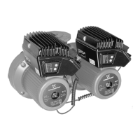
The UPE Series 2000 is designed for circulating liq-
uids in heating systems. The pumps can also be
used in domestic hot-water systems.
UPE Series 2000 is suitable for:
• systems with a constant flow where it is desira-
ble to optimize the setting of the pump duty point
and
• systems with variable flow-pipe temperatures.
2.1 Pumped liquids
Thin, clean, non-aggressive and non-explosive liq-
uids, not containing solid particles, fibres or mineral
oil.
In heating systems, the water should meet the
requirements of accepted standards on water quality
in heating systems, e.g. the German standard VDI
2035.
In domestic hot-water systems, it is advisable to
use UPED pumps only for water with a degree of
hardness lower than approx. 14°dH.
For water with a higher degree of hardness a direct-
coupled TPE pump is recommended.
3. Installation
When installing pumps, types UPED 50-xx and
65-xx, with oval bolt holes in the pump flange,
washers must be used as shown in fig. 2.
Fig. 2
See mounting dimensions at the end of these
instructions.
The pump must be installed with the motor shaft hor-
izontal.
Arrows on the pump housing indicate the liquid flow
direction through the pump.
The permissible liquid flow directions through the
pump are indicated by an "X" in the following table:
Note: Pumps mounted in horizontal pipes must be
fitted with an automatic air vent in the upper part of
the pump housing.
The automatic air vent is not supplied with the pump.
3.1 Terminal box positions
The terminal box can be turned to the positions
shown in figure 3.
Note: The terminal box must only be turned to the
positions below.
Fig. 3
3.2 Changing the terminal box position
Change the terminal box position as follows:
1. Remove the four screws holding the pump head.
2. Turn the pump head to the required position.
3. Replace the four screws and tighten securely.
The pump must not be used for the trans-
fer of inflammable liquids such as diesel
oil, petrol or similar liquids.
TM01 0683 1997
Care should be taken to ensure that per-
sons cannot accidentally come into con-
tact with hot surfaces of the pump.
Installation
Pump
Washer
Liquid flow
direction
TM02 1389 1101
TM02 1391 1101
TM02 1392 1101
TM02 1393 1101
Pump type
UPED 50-120 X X X
UPED 65-120 X X X
UPED 80-120 X X X
UPED 100-60 X X X
→
TM02 2104 3401
Before any dismantling of the pump, the
system must be drained or the isolating
valves on either side of the pump must be
closed as the pumped liquid may be scald-
ing hot and under high pressure.
 Loading...