EasyManua.ls Logo

Grundig 32 GLX 6052 User Manual

Grundig 32 GLX 6052
63 pages
To Next Page IconTo Next Page
Page #1 background imageLoading...
Page #1 background image
TV Service Manual
Zusätzlich erforderliche Unterlagen für den Komplettservice
Additionally required Service Documents for the Complete Service
Service
Manual
Sicherheit
Safety
Materialnr./Part No.
720108000001
Chassis TD
32 GLX 6052 GBI6432
32 GLX 6951 GBH8136
37 GLX 6052 GBI6037
37 GLX 6951 GBH8138
42 GLX 6052 GBI6142
Vision 6
32-6950 GBH8532
37-6950 GBH8537
42-6950 GBH8542
Chassis TE
26 GLX 4000 GBI2126
32 GLX 2600 GBJ2832
32 GLX 4000 GBI2132
NUR FÜR INTERNEN GEBRAUCH
FOR INTERNAL USE ONLY
Materialnummer / Part Number 720100551000
Änderungen vorbehalten / Subject to alteration
TCC 1010 0112 MP • Prepared in Germany
http://www.grundig.com
Question and Answer IconNeed help?

Do you have a question about the Grundig 32 GLX 6052 and is the answer not in the manual?

Grundig 32 GLX 6052 Specifications

General IconGeneral
Screen Size32 inches
Display TechnologyLCD
Backlight TechnologyLED
Aspect Ratio16:9
TunerDVB-T/C/S2
USB Port1
VGA Port1
SCART Port1
CI Slot1
Energy Efficiency ClassA
Wi-FiNo
Resolution1366 x 768 pixels
HD SupportHD Ready
Power Consumption (Standby)0.5 W

Summary

Service Manual Overview

Chassis TD and TE Model Identification

Lists TV models for Chassis TD and TE with associated order numbers.

General Section and Component Layouts

General Notes and Safety Precautions

Safety guidelines and general handling instructions for service.

PCB Layouts and Circuit Diagrams

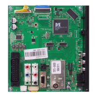
Overview of main board layouts and circuit diagrams for TV components.

Product and Display Variant Information

Display and Product Code Identification

Guidance on identifying product codes and display variants for service.

Detailed Technical Specifications

Model-Specific Technical Data

Comprehensive technical data tables for various TV models and chassis.

Operating Instructions and Controls

Remote Control Button Functions

Explanation of the functions assigned to each button on the remote control.

Child Lock Feature Management

Step-by-step guide to activate and deactivate the child lock feature.

Operational Hints and Settings

Connecting External Devices to TV

Instructions for connecting external audio and video sources.

Parental Lock Configuration

Procedures for setting up and managing parental control features.

External Device Integration

PC Connectivity and Setup Guide

Steps for connecting a PC and configuring display settings.

Service Mode and Special Functions

Service Mode Access Procedure

Method to enter the service mode using remote control codes.

Basic Settings Configuration Table

Table listing essential settings for different models in service mode.

Chassis Board Component Layout

YTD190R-7 Component Side Identification

Diagram showing component placement on the YTD190R-7 chassis board.

Circuit Schematics - Core Components

Power Supply Unit (FSP115-3F01) Schematic

Schematic diagram for the FSP115-3F01 power supply.

TV Tuner Module Schematic

Circuit diagram detailing the TV tuner functionality.

SCART Interface Circuit Diagram

SCART Connector Circuitry Details

Schematic illustrating the SCART connection interface.

AV, VGA, and USB Interface Schematics

AV, VGA, USB Port Connectivity

Circuit diagrams for AV, VGA, and USB input ports.

HDMI Interface Circuit Diagrams

HDMI Input Port Circuitry

Schematic detailing the HDMI connection interface and signal paths.

Scaler IC and Related Circuitry

MST69981DLD-LF-S1 Scaler IC Schematic

Circuit diagram for the scaler IC and its supporting components.

Audio Amplifier and Speaker Circuitry

STA335BW Amplifier IC Schematic

Schematic of the audio amplifier IC and speaker output connections.

Power Supply Unit Schematics (FSP115-3F01)

FSP115-3F01 Component Side View

Component layout diagram for the FSP115-3F01 PSU.

Power Supply Unit Schematics (FSP115-3F02)

FSP115-3F02 Component Side View

Component layout diagram for the FSP115-3F02 PSU.

Power Supply Unit Schematics (FSP223-3F01)

FSP223-3F01 Component Side View

Component layout diagram for the FSP223-3F01 PSU.

Peripheral Component Identification

IR Receiver and Keyboard Identification Diagrams

Identification diagrams for IR receivers and keyboards.

Spare Parts List - Chassis TD/TE Models

Spare Parts for 26 GLX 4000

List of spare parts for the 26 GLX 4000 TV model.

Spare Parts for 32 GLX 2600

List of spare parts for the 32 GLX 2600 TV model.

Spare Parts List - Continued

Spare Parts for 32 GLX 4000

List of spare parts for the 32 GLX 4000 TV model.

Spare Parts for 32 GLX 6052

List of spare parts for the 32 GLX 6052 TV model.

Spare Parts List - Continued

Spare Parts for 37 GLX 6052

List of spare parts for the 37 GLX 6052 TV model.

Spare Parts for 32 GLX 6951

List of spare parts for the 32 GLX 6951 TV model.

Spare Parts List - Continued

Spare Parts for 42 GLX 6052

List of spare parts for the 42 GLX 6052 TV model.

Spare Parts for 37 GLX 6951

List of spare parts for the 37 GLX 6951 TV model.

Spare Parts List - Continued

Spare Parts for Vision 6 32-6950

List of spare parts for the Vision 6 32-6950 model.

Spare Parts for Vision 6 37-6950

List of spare parts for the Vision 6 37-6950 model.

Spare Parts List - Continued

Spare Parts for Vision 6 42-6950

List of spare parts for the Vision 6 42-6950 model.

Chassis Board Component Listings

TD/TE Chassis Board Components

List of components and their part numbers for the TD/TE chassis board.

Power Supply Component Listings

FSP115-3F01 PSU Components

List of components for the FSP115-3F01 power supply unit.

Power Supply Component Listings (Continued)

FSP115-3F02 PSU Components

List of components for the FSP115-3F02 power supply unit.

Power Supply Component Listings (Continued)

FSP223-3F01 PSU Components

List of components for the FSP223-3F01 power supply unit.

Related product manuals