Allgemeiner Teil / General Section
1 - 4 GRUNDIG Service
Apollo 2000
3.1 Verstärker-Platten
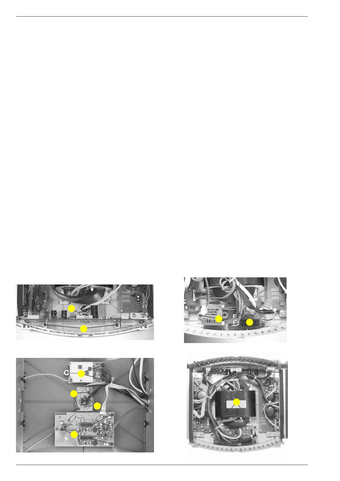
- Je 2 Schrauben D (Fig. 4), 4 Schrauben E (Fig. 5) und 2
Schrauben F (Fig. 5) herausschrauben.
- Steckverbinder nach Bedarf lösen.
- Kabelbinder nach Bedarf lösen.
- Verstärker-Platten mit Kühlkörper herausnehmen.
3.2 Control-Platte
- 2 Schrauben G (Fig. 6) und Schraube H (Fig. 6)
herausschrauben.
- Steckverbinder nach Bedarf lösen.
- Kabelbinder nach Bedarf lösen.
3.3 Netzanschluss-Platte
- 4 Schrauben I (Fig. 7) herausschrauben.
- Steckverbinder nach Bedarf lösen.
3.4 Audio-Funk-Modul
- 3 Schrauben K (Fig. 8) herausschrauben.
- Steckverbinder nach Bedarf lösen.
3.5 Daten-Funk-Modul
- 3 Schrauben L (Fig. 8) herausschrauben.
- Steckverbinder nach Bedarf lösen.
3.6 Netzschalter-Platte
- 2 Schrauben M (Fig. 8) herausschrauben.
- Steckverbinder nach Bedarf lösen.
4. Standby-Transformator
- Lautsprechereinheit ausbauen (Punkt 1).
- 2 Schrauben N (Fig. 7) herausschrauben.
- Steckverbinder nach Bedarf lösen.
- Kabelbinder nach Bedarf lösen.
5. Transformator
- Lautsprechereinheit ausbauen (Punkt 1).
- 4 Schrauben O am Trafo herausschrauben (Fig. 9).
- Steckverbinder nach Bedarf lösen.
- Kabelbinder nach Bedarf lösen.
6. Netzschalter
- Lautsprechereinheit ausbauen (Punkt 1).
- Schalterknopf abziehen.
- Netz-LED-Platte ausbauen (Punkt 3.6).
- 2 Schrauben P (Fig. 8) herausschrauben.
- Steckverbinder nach Bedarf lösen.
Fig. 8
L
K
M
P
Fig. 6
G
H
Fig. 7
I
N
3.1 Amplifier Boards
- Undo 2 screws D (Fig. 4), 4 screws E (Fig. 5) and 2 screws F
(Fig. 5) each.
- Disconnect the connectors if necessary.
- Open the cable supports if necessary.
- Remove the amplifier boards together with the cooling plate.
3.2 Control PCB
- Undo 2 screws G (Fig. 6) and screw H (Fig. 6).
- Disconnect the connectors if necessary.
- Open the cable supports if necessary.
3.3 Mains Connecting PCB
- Undo 4 screws I (Fig. 7).
- Disconnect the connectors if necessary.
3.4 Audio RF Module
- Undo 3 screws K (Fig. 8).
- Disconnect the connectors if necessary.
3.5 Data RF Module
- Undo 3 screws L (Fig. 8).
- Disconnect the connectors if necessary.
3.6 Mains Switch PCB
- Undo 2 screws M (Fig. 8).
- Disconnect the connectors if necessary.
4. Standby Transformer
- Remove the speaker unit (para 1).
- Undo 2 screws N (Fig. 7).
- Disconnect the connectors if necessary.
- Open the cable supports if necessary.
5. Transformator
- Remove the speaker unit (para 1).
- Undo 4 screws O from the transformer (Fig. 9).
- Disconnect the connectors if necessary.
- Open the cable supports if necessary.
6. Mains Switch
- Remove the speaker unit (para 1).
- Pull off the power knob.
- Remove the mains LED PCB (para 3.6).
- Undo 2 screws P (Fig. 8).
- Disconnect the connectors if necessary.
Fig. 9
O