Chassis D5GRUNDIG Service
1 - 13
TDA6108 Triple Video Output Amplifiers
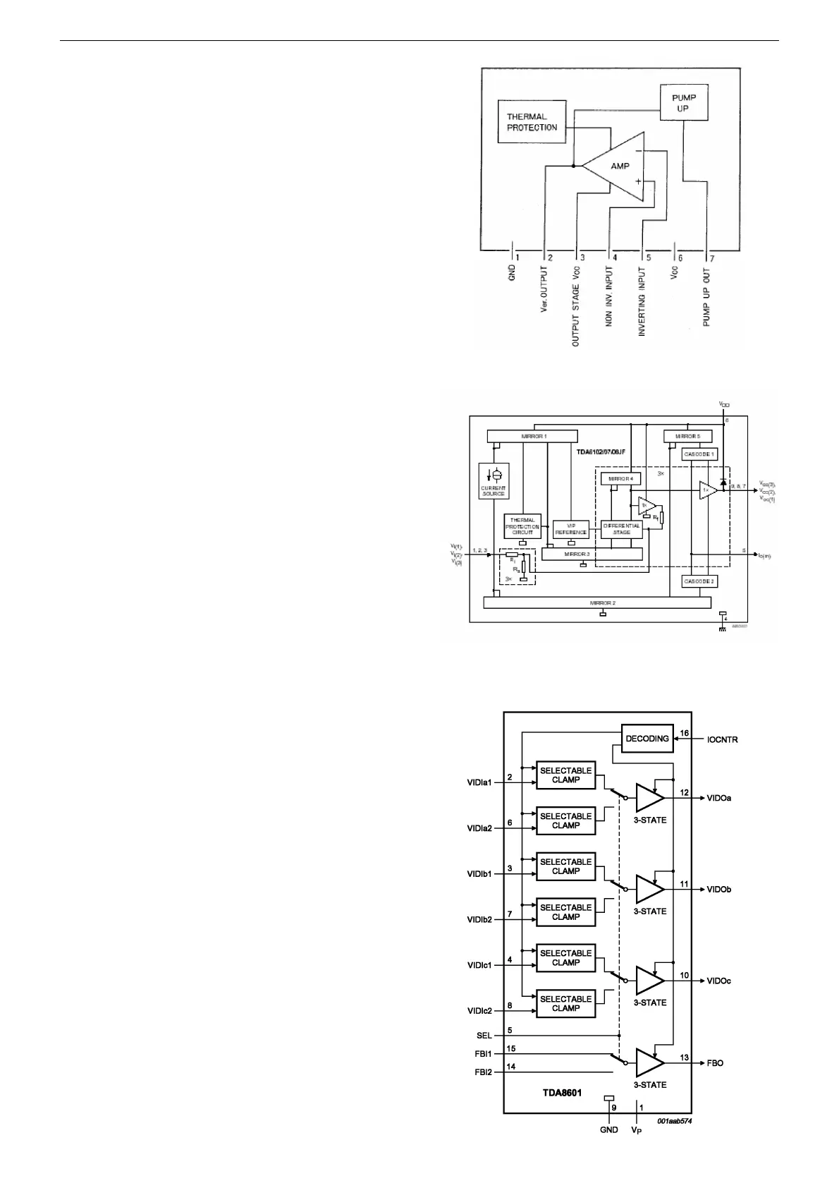
By integrating three video amplifiers in a single IC, the TDA6108
ICs provides a single IC solution for driving color TV CRTs. Each
device in the TDA6108 family contains three video output amplifiers
in one plastic DIL-bent-SIL 9-pin medium power (DBS9MPF) packa-
ge (SOT111-1). Using high-voltage DMOS technology, this enables
each of these ICs to drive the three cathodes of a color CRT di-
rectly, providing a significant reduction in the Bill of Materials for
new designs. For maximum performance, the TDA610x amplifiers
should be used with black-current control, enabling automatic black
current stabilization and removing the need for any external align-
ments on the CRT board.
LA7840 Vertical Deflection Output Circuit
Features
• Low power dissipation due to built-in pump-up circuit
• Vertical output circuit
• Thermal protection circuit built in
• Excellent crossover characteristics
• DC coupling possible
General Description
The LA7840 is a vertical deflection output IC for TVs and CRT dis-
plays with excellent image quality that use a BUS control system si-
gnal processing IC. This IC can drive the direct (even including a
DC component) deflection yoke with the sawtooth wave output from
the BUS control system signal processing IC. Because the maxi-
mum deflection current is 1.8 Ap-p, the LA7840 is suited for small
and medium screen sets.
TDA8601 RGB/YUV and Fast Blanking Switch
Features
• YUV/RGB and fast blanking switch
• 3-state output
• Selectable clamp:
– passive (with diodes) or active clamp
• Bandwidth greater than 22MHz
• Fully ESD protected
• Latch-up free.
General Description
The device is intended for switching between two RGB or YUV vi-
deo sources. The outputs can be set to a high-impedance state to
enable parallel connection of several devices. A HIGH level on SEL
(pin 5) selects the video inputs of Channel 2. The IOCNTR control
pin (pin 16) defines the 3-state outputs and clamp inputs:
• HIGH = 3-state outputs (also for test; active clamp)
• LOW = passive clamp at the video inputs (diode)
• Sandcastle: the video signal is clamped with an active clamp du-
ring the sync pulse.



 To Next Page