Do you have a question about the Grundig FINE ARTS CD 9000 and is the answer not in the manual?
Details on audio signal conversion and quality.
Specifications for the laser pickup.
Electrical requirements and consumption.
Procedures for attaching and removing surface-mount parts.
Detailed steps for removing surface-mount components.
Detailed steps for attaching surface-mount components.
Safety rules applicable across regions.
Specific safety guidelines for the US market.
Groups servicing aids and general safety warnings.
Groups safety tests, equipment, and procedures.
Guidelines for performing repairs.
Detailed safety measures for MOS components.
Specific soldering guidelines for MOS components.
Steps to access internal components.
Procedure to remove the decoder circuit board.
Procedure to remove the front panel.
Procedures for removing various internal panels.
Procedure to remove the CD loading tray.
Detailed steps for removing decoder and display panels.
Detailed steps for removing processor and servo panels.
Detailed procedure for removing the disc tray.
List of external and loading mechanism parts.
List of mechanical parts for the drive.
List of electronic components.
List of components specific to the CD drive mechanism.
List of components specific to the CD drive mechanism.
List of electronic components.
List of various electronic components by type.
List of parts for the servo and power supply boards.
List of various electronic components by type.
List of various electronic components by type.
List of various electronic components by type.
Description of the CD disc structure and information storage.
Information on disc rotational speeds and related parameters.
Details on disc size, track layout, and pit dimensions.
Explanation of data blocks, frames, and subcode.
Illustration of disc layout and dimensions in millimeters.
Explanation of how laser light is generated and used.
Description of the injection laser diode and its function.
Details on laser light characteristics and safety viewing.
Process of converting analog audio to digital 16-bit words.
Explanation of sidebands and potential signal interference.
Diagram showing audio signal conversion to 16-bit data.
Function of the sample and hold circuit in data acquisition.
How a 1-bit reading error affects the signal.
Use of block coding (FRAME) and parity bits for error correction.
Using interleaving to manage data loss from disc scratches.
Illustration of signal processing before and after interleaving.
Visual representation of data loss without interleaving.
Visual representation of data recovery with interleaving.
Using NRZ code to save bandwidth and increase storage density.
Eight to Fourteen Modulation for data symbol encoding.
Use of merging bits to balance DC voltage in data transmission.
Tools and equipment recommended for service.
Procedures for checking and adjusting laser power supply.
Details on audio signal conversion and quality.
Specifications for the laser pickup.
Electrical requirements and consumption.
Steps to enter the microprocessor service mode.
Explanation of the different microprocessor service states.
Procedure to safely exit the service mode.
Procedures for removing the CD drive and laser assembly.
Cautionary note for reassembling the laser unit.
Steps for coarse and fine adjustment of laser power.
Detailed steps for the final laser power adjustment.
Procedures for verifying laser power supply.
Checking the ready signal indicating focal point acquisition.
Verification of high-frequency input and output signals.
Testing detector, dropout, and track loss signals.
Verification of radial error signals.
Checks for dropout, start capacitor, and focus error lag signals.
Diagnostics for the radial error processor.
Checks for radial error digital, DAC, and radial error signals.
Verification of key signals for the decoder µP.
Verification of additional decoder µP signals.
Verification of signals related to motor control and audio processing.
Checks for clock and timing signals.
Checks for error flags and Q-channel data.
Checks for specific data and error signals.
Diagnostics for the Filter-B IC.
Verification of signals between ICs.
Verification of signals between Filter-B and DAC.
List of various electronic components by type.
List of various electronic components by type.
List of parts for the CD loading mechanism.
List of mechanical and electrical parts.
Explanation of the different service modes.
Procedures for disassembling the CD loading tray.
Detailed procedures for installing the tray mechanism.
List of parts for the servo and preamplifier boards.
List of parts for the decoder and power supply boards.
List of parts for the CD loading mechanism.
List of electronic components.
List of parts for the servo and preamplifier boards.
List of parts for the decoder and power supply boards.
List of parts for the CD loading mechanism.
List of mechanical and electrical parts.
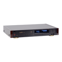
| Type | CD Player |
|---|---|
| Frequency Response | 20 Hz - 20 kHz |
| Output Voltage | 2 V |
| Digital Output | Coaxial |
| Remote Control | Yes |
| Signal-to-Noise Ratio | 100 dB |
| Dynamic Range | 96 dB |