Allgemeiner Teil / General Section M 7-C / M 17-C / M 27-C
1 - 12 GRUNDIG Service
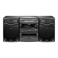
21. Ausbau der Cassettenlaufwerke (Fig. 33)
- Die Frontblende ausbauen (Pkt. 3).
- 4 Schrauben a (lang) herausdrehen.
- 4 Schrauben b (kurz) herausdrehen.
- Beide Cassettenfachdeckel durch Drücken der Tasten "Eject" öff-
nen.
- Beide Laufwerke abnehmen.
21. Removing the Drive Mechanisms (Fig. 33)
- Remove the front panel (para 3).
- Unscrew 4 screws a (long).
- Unscrew 4 screws b (short).
- Open both cassette compartment lids by pressing the buttons
"Eject".
- Remove both drive mechanisms.
aaaa
bbbb
c
c
ed
f
g
f
g
Kopfsteckerplatte
Head Connector Board
Fig. 36
Fig. 37
Fig. 34
Fig. 35
Fig. 33
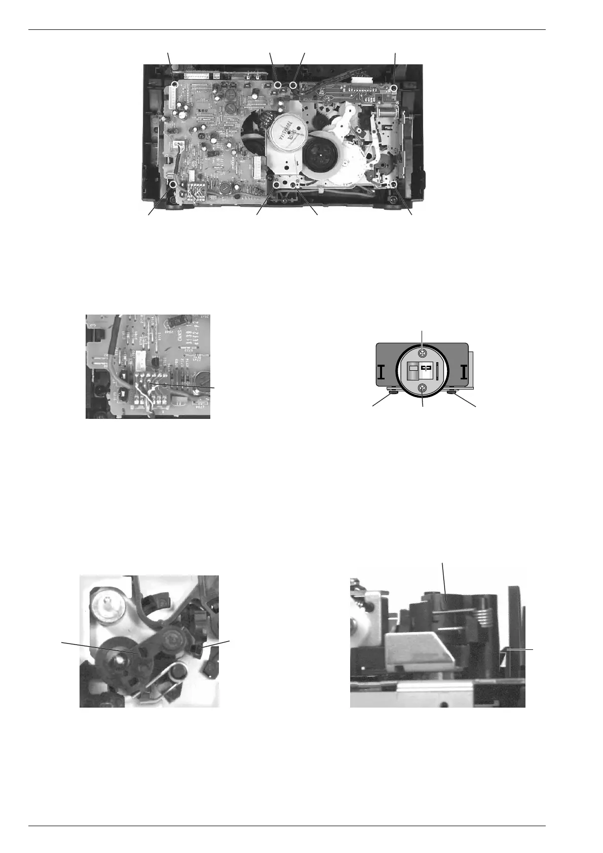
22. Auswechseln des A-W-Drehkopfes (Fig. 34 / 35)
- Die Cassettenlaufwerke ausbauen (Pkt. 21).
- Kopfleitungen von der Kopfsteckerplatte (Stecker 1720 Fig. 34)
ablöten, vorher Anschlüsse notieren.
- 2 Schrauben c (Fig. 35) herausdrehen und den Tonkopf heraus-
nehmen.
- Neuen Tonkopf einsetzen und in umgekehrter Reihenfolge zusam-
menbauen.
Die Schrauben d und e (Fig. 35) dienen zur Kopfspaltsenkrecht-
stellung (Azimut) und dürfen nicht festgedreht werden.
Kopfspaltsenkrechtstellung siehe unter Abgleichvorschriften Sei-
te 2 - 2.
23. Ausbau eines Andruckrollenhebels (Fig. 36 / 37)
- Die Cassettenlaufwerke ausbauen (Pkt. 21).
- Rastnase f vorsichtig ausrasten und den Andruckrollenhebel g
abziehen.
22. Replacing the R-P-Rotary Head (Fig. 34 / 35)
- Remove the drive mechanisms (para 21).
- Unsolder the headleads from the head connector board (connector
1720 Fig. 34). Before this, note down the connections.
- Unscrew 2 screws c (Fig. 35) and remove the sound head.
- Fit the new sound head and re-assemble in reverse order.
The screws d and e (Fig. 35) are provided for adjusting the head
gap (azimuth) and must not be tightened completely.
Adjustment of the head gap, see Adjustments page 2 - 4.
23. Removing a Pressure Roller Lever (Fig. 36 / 37)
- Remove the drive mechanisms (para 21).
- Disengage the locking lug f carefully and pull out the pressure
roller lever g.
 Loading...