Do you have a question about the Grundig ovation cds 6580 spcd and is the answer not in the manual?
Lists test equipment like signal generators, oscilloscopes, etc.
Safety precautions, wiring, measurement guidelines, and measured value notes.
Power supply, mains frequency, power consumption, amplifier output.
Reception ranges, frequency response, MP3 features, dimensions, and weight.
Safety rules for ESD and specific instructions for handling the CD laser unit.
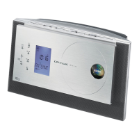
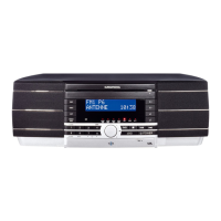
Details on buttons and functions on the front of the HiFi system.
Describes buttons and functions located on the top of the HiFi system.
Explains controls on the sides and bottom of the HiFi system.
Explains the meaning of various symbols and text shown on the HiFi display.
Details the functions of each button on the remote control.
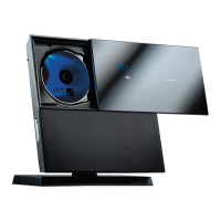
Step-by-step guide on how to open the device cabinet safely.
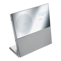
Instructions on how to remove the display flap assembly.
Procedures for aligning the AM Intermediate Frequency and oscillator.
Procedures for aligning AM bandpass and FM IF circuits.
Procedure for aligning the FM 19kHz filter.
High-level overview of the system's functional blocks and their connections.
Detailed schematic showing all internal wiring connections between components.
Detailed circuit diagram for the power supply unit.
Detailed circuit diagram for the audio processing and amplification sections.
Circuit diagrams for the CD player control and microcontroller units.
Circuit diagram for the display and keyboard interface.
Detailed circuit diagram for the radio tuner section.
Internal block diagrams of key integrated circuits used in the system.
Illustrated diagrams showing the physical assembly of the device's components.
A catalog of all replaceable parts with their part numbers and descriptions.
| Brand | Grundig |
|---|---|
| Model | ovation cds 6580 spcd |
| Category | Stereo System |
| Language | English |