Do you have a question about the Grundig OVATION CDS 7000 SPCD and is the answer not in the manual?
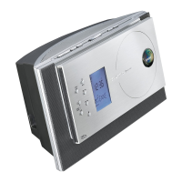
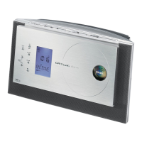
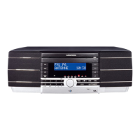
Identifies and describes the main physical controls on the hi-fi unit.
Explains the various indicators and display segments of the hi-fi system.
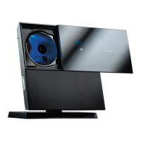
Details the functions and interface for USB device operation.
Describes the functions of buttons on the remote control unit.
Provides visual exploded views and identification of parts for disassembly.
Details the adjustment procedures and test equipment for the tuner section.
Presents the overall functional block diagram of the hi-fi system.
Illustrates the electrical interconnections between different boards and components.
Details the schematic and PCB layout for the power supply unit.
Provides circuit diagrams for the audio processing section, including IC details.
Details circuit schematics and IC block diagrams for the CD and microcontroller unit.
Provides circuit diagrams and IC block diagrams for the USB interface.
Shows the schematic and PCB layout for the front display unit.
Details the PCB layouts for Keyboard, AUX-IN, and IR Sensor modules.
Presents tuner schematics, IC details, and component layouts.
| Brand | Grundig |
|---|---|
| Model | OVATION CDS 7000 SPCD |
| Category | Stereo System |
| Language | English |