Zusätzlich erforderliche Unterlagen für den Komplettservice
Additionally required Documents for the Complete Service
Service
Manual
Service Manual
Dieses Service Manual ist nur in Datenform verfügbar
This Service Manual is only available as data
Änderungen vorbehalten
Subject to alteration
Made by GRUNDIG in Germany
E-BS 36 1199
http://www.grundig.com
Sicherheit
Safety
Materialnr./Part No.
72010 800 0000
GB
Table of Contents
Page
Adjustment Procedures.......................... 3 … 5
Circuit Diagrams
and Layout of PCBs .............................. 6 … 32
Circuit Diagrams
RF Part ....................................................................................... 6
Processor Part .......................................................................... 10
Operating Board ....................................................................... 14
AF Part...................................................................................... 17
Sound Module........................................................................... 21
Connection Board ..................................................................... 23
Layout of PCBs ............................................................................ 25
Spare Parts Lists and
Exploded View..................................... 33 … 38
Spare Parts List and Exploded View Tape Drive ......................... 33
Spare Parts List Smartradio ......................................................... 35
Spare Parts List Smartradio CC................................................... 37
D
Inhaltsverzeichnis
Seite
Abgleichvorschriften .............................. 2 … 5
Schaltpläne und
Druckplattenabbildungen ..................... 6 … 32
Schaltpläne
HF-Teil ........................................................................................ 6
Prozessor-Teil ........................................................................... 10
Bedienplatte .............................................................................. 14
NF-Teil ...................................................................................... 17
Soundmodul .............................................................................. 21
Anschlußplatte .......................................................................... 23
Druckplattenabbildungen .............................................................. 25
Ersatzteillisten und
Explosionszeichnung ......................... 33 … 38
Ersatzteilliste und Explosionszeichnung Laufwerk ...................... 33
Ersatzteilliste Smartradio ............................................................. 35
Ersatzteilliste Smartradio CC ....................................................... 37
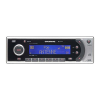
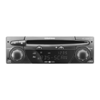
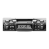
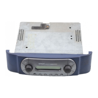
Service-Management
Smartradio (G.HH 75-00)
Smartradio CC (G.HH 76-00)