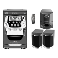
UMS 1 / UMS 2 Allgemeiner Teil / General Section
GRUNDIG Service 1 - 19
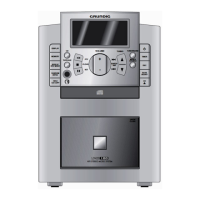
Fig. 18
12. CD-Laufwerk ausbauen
- CD-Teil ausbauen (Pkt. 3).
- 4 Schrauben A herausdrehen (Fig. 19).
- CD-Laufwerk herausnehmen.
Achtung! Verstellen Sie den Regler für die Laserstromeinstellung
nicht. Der Laserstrom wurde werkseitig eingestellt.
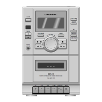
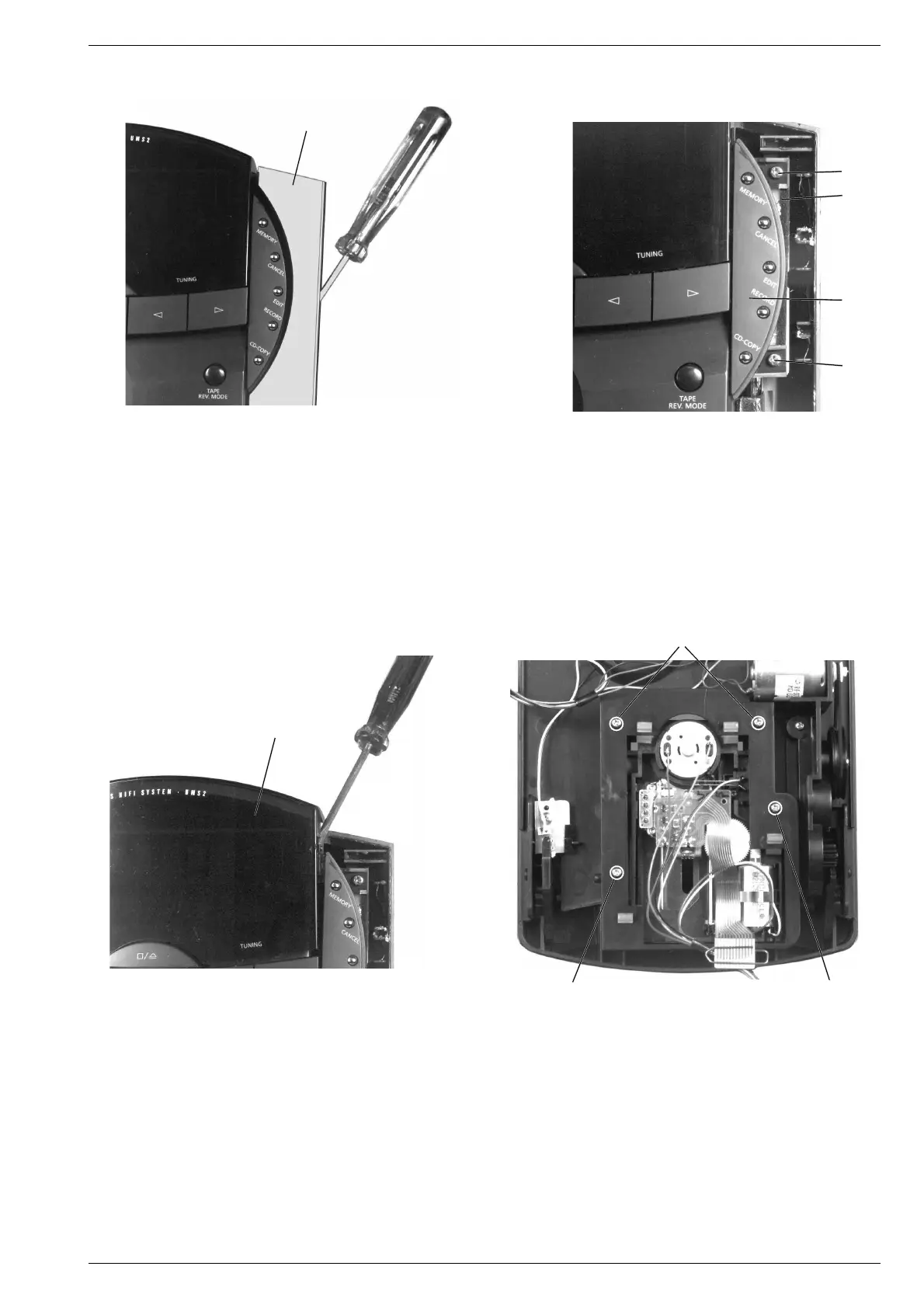
Fig. 16
Fig. 17
10. Linke bzw. rechte Tastenplatte ausbauen
- Vorsichtig die aufgeklebte seitliche Blende v mit einem Schrau-
bendreher abhebeln (Fig. 16).
- 2 Schrauben w herausdrehen (Fig. 17).
- Tastenplatte x mit Tastenabdeckung y herausnehmen.
11. Displayabdeckung ausbauen
- Linke und rechte Tastenplatte ausbauen (Pkt. 10).
- Vorsichtig die aufgeklebte Displayabdeckung z mit einem
Schraubendreher abhebeln (Fig. 18).
10. Removing the Keyboard PCB, left or right
- Lift off the glued lateral mask v carefully with a screw driver
(Fig. 16).
- Undo 2 screws w (Fig. 17).
- Take out the keyboard PCB x with the keyboard cover y.
11. Removing the Display Cover
- Remove the keyboard PCB, left and right (para 10).
- Lift off the glued display cover z carefully with a screw driver
(Fig. 18).
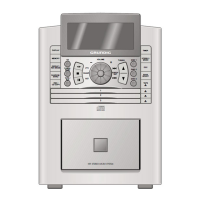
Fig. 19
12. Removing the CD Drive Mechanism
- Remove the CD unit (para 3).
- Undo 4 screws A (Fig. 19).
- Take out the CD drive mechanism.
Attention! Do not turn the variable resistor for laser power adjustment.
The laser current is pre-set at the factory.
v
w
y
z
A
A
A
w
x