UMS 1 / UMS 2 Allgemeiner Teil / General Section
GRUNDIG Service 1 - 21
X
2
1
20. Tonkopf auswechseln
- Laufwerk ausbauen (Pkt. 13).
- Kopfleitungen von der Kopfanschlußplatte ablöten (Anschlüsse
notieren).
- Kopfleitungen aus den Kabelhaltern aushängen.
- 2 Schrauben X herausdrehen und den Tonkopf herausnehmen
(Fig. 29).
- Neuen Tonkopf einsetzen und in umgekehrter Reihenfolge zusam-
menbauen.
Die Kopfschrauben 1 und 2 dienen der Kopfspaltsenkrecht-
stellung (Azimut) und dürfen nicht festgedreht werden.
Kopfspaltsenkrechtstellung siehe unter Einstellungen.
Fig. 28
1
2
1
L
M
2
3
U
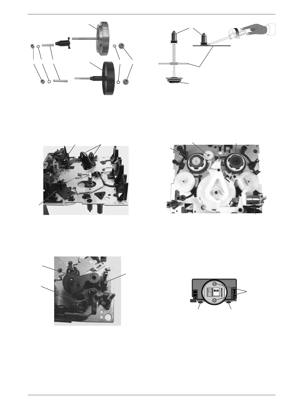
19. Andruckrolle auswechseln
- Laufwerk ausbauen (Pkt. 13).
- Untere Drehfeder T aushängen (Fig. 26).
- Rastnase U (Fig. 28) ausrasten und die Andruckrolle V mit der
Drehfeder W abziehen.
- Beim Einbau ist die Feder T (Fig. 26) wieder einzuhängen.
Fig. 26
19. Replacing the Pressure Roller
- Remove the drive mechanism (para 13).
- Unhook the lower torsion spring T (Fig. 26).
- Disengage the locking lug U (Fig. 28) and pull out the pressure
roller V with the torsion spring W.
- Refit the spring T (Fig. 26) when mounting the new pressure roller.
Fig. 27
SERVOMAGNET
18. Kupplungen ausbauen
- Laufwerkplatte ausbauen (Pkt. 16).
- Schwungräder ausbauen (Pkt. 17).
- Scheibe G und Riemenscheibe O abziehen (Fig. 23).
- Wickeldorn P aushebeln und abziehen (Fig. 25 und 26).
- Bei Bedarf das Zahnrad Q abziehen (Fig. 27).
- Nehmen Sie die Kupplungen R/S nach hinten heraus.
Vorlaufkupplung
Forward clutch
P
Magnet
Fig. 24 Fig. 25
18. Removing the Clutches
- Remove the drive mechanism circuit board (para 16).
- Remove the flywheels (para 17).
- Pull off the washer G and the pulley O (Fig. 23).
- Lift off and remove the spindle P (Figs. 25 and 26).
- If necessary pull off the gearwheel Q (Fig. 27).
- Remove the clutches R/S towards the rear.
Chassis
S
Q
R
T
P
T
V
W
Fig. 29
20. Replacing the Sound Head
- Remove the drive mechanism (para 13).
- Unsolder the head leads from the head connecting board (note
down the connections).
- Detach the head leads from the cable holders.
- Undo 2 screws X and remove the sound head (Fig. 29).
- Fit the new sound head and re-assemble in reverse order.
The head screws 1 and 2 are provided for adjusting the head gap
(azimuth) and must not be tightened completely.
Adjustment of the head gap, see Adjustments.




 To Next Page