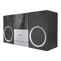
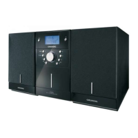
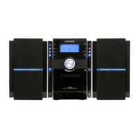
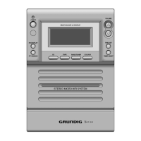
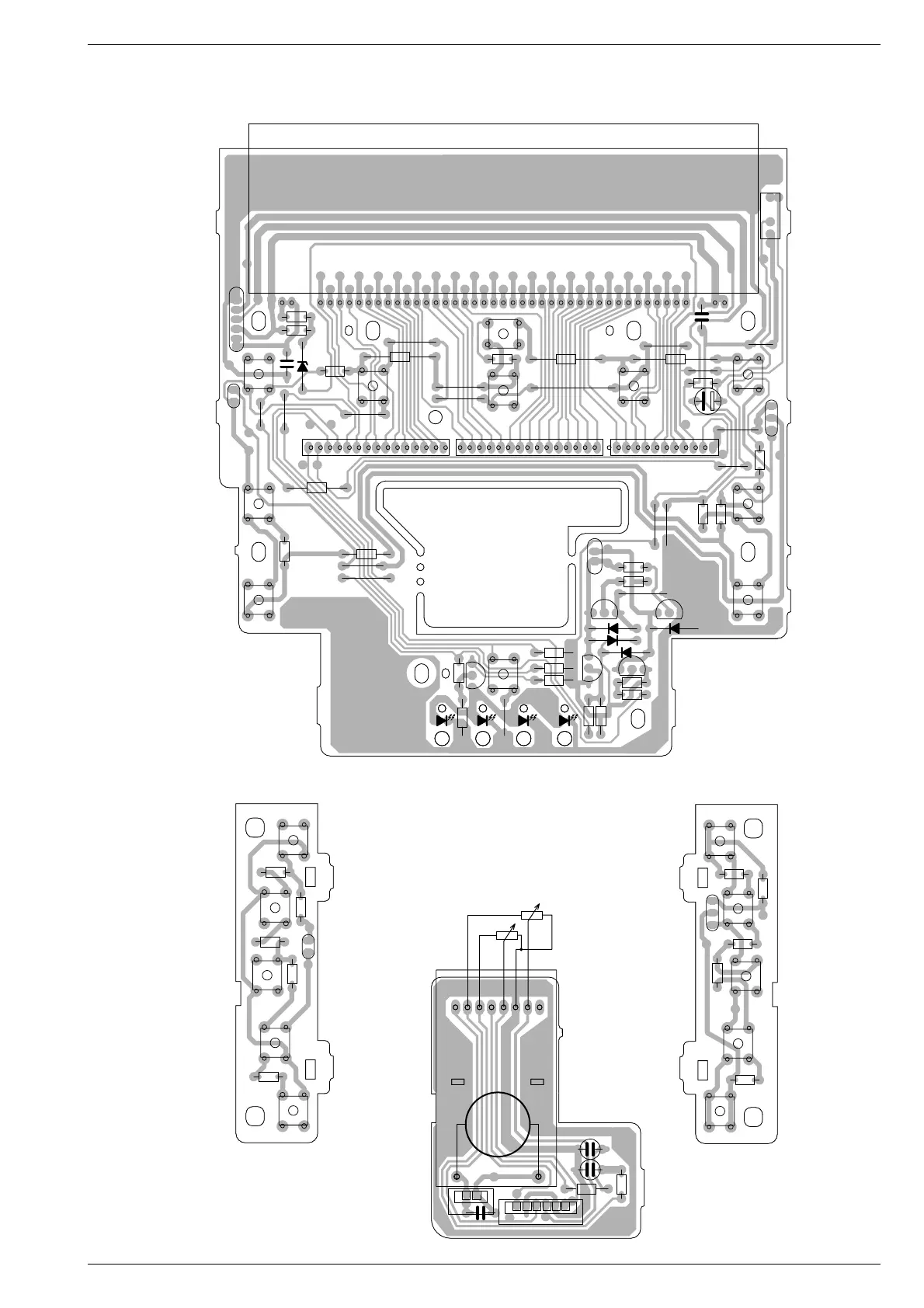
UMS 1 / UMS 2 Schaltpläne und Platinenabbildungen / Circuit Diagrams and Layout of PCBs
3 - 9GRUNDIG Service
Für die tatsächliche Bauteilebestückung
ist das Schaltbild maßgebend.
The circuit diagram is relevant for the
actual component assembly.
R647
TC606
1234567 8
M1
M2
VR601
P
C609
R646
CN613
C611
P
C610
LOUT
LIN
RIN
ROUT
GND
GND
CN604
S613
S611
S615
S614
S612
R616
R615
R614
R613
R612
CN602
S620
S619
S616
S618
S617
R620
R621
R619
R618
R617
R625
R649
JP611
JP610
TC609
TC611
JP612
JP607
JP603
JP606
JP608
JP601
JP604
JP614
JP605
JP609
R606
JP602
R607
JP613
FC605
FC603
R609
JP615
DP601
JP616
CE
T603
R648
D601
D604
D603
EC
T604
TC601
S609
S610
S603
S608
S607
S621
S601
S602
S606
S605
R602
R636
R610
R634
R603
R629
R628
JP617
R624
R627
R626
R635
R611
R601
R608
R623
C612
R605
R604
EC
T605
RC601
R650
TC610
+
C608
D606
CE
T602
C635
D602
EC
T601
R633
S604
TC612
530.0294.01
Leiterplatten / PCBs
Bestückungsseite
Component side
Bedienplatte / Keyboard Control PCB
Tastenplatte links
Keyboard left
Tastenplatte rechts
Keyboard right
Lautstärkereglerplatte
Volume Control PCB
VR601
L
R
M
1
1
11
1
1
1
1
1