Programming Chapter Five Tool Nose Radius Compensation(G41,G42)
243
Chapter 5 Tool Nose Radius Compensation (G41,G42)
5.1 Application
5.1.1 Overview
Part program is compiled generally for one point of tool according to a workpiece contour. The point
is generally regarded as the tool nose A point in an imaginary state (there is no imaginary tool nose point
in fact and the tool nose radius can be omitted when using the imaginary tool nose point to program) or
as the center point of tool nose arc ( as Fig. 5-1). Its nose of turning tool is not the imaginary point but
one arc owing to the processing and other requirement in the practical machining. There is an error
between the actual cutting point and the desired cutting point, which will cause the over- or under-cutting
affecting the part precision. So a tool nose radius compensation is needed in machining to improve the
part precision.
B tool compensation is defined that a workpiece contour path is offset one tool nose radius, which
cause there is excessive cutting at an intersection of two programs because of executing motion path of
next after completing the previous block.
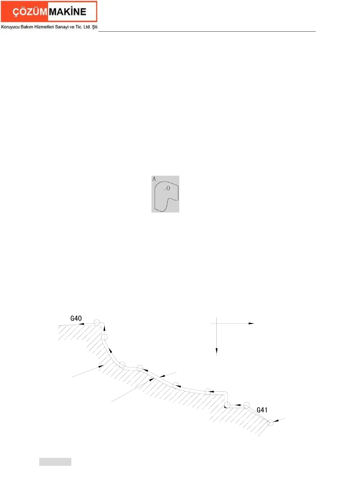
To avoid the above-mentioned ones, the system uses C tool compensation method (namely, tool
nose radius compensation). The system will read the next block instead of executing it immediately after
reading a block in C tool compensation method, and count corresponding motion path according to
intersection of blocks. Contour can be compensated precisely because reading two blocks are
pretreated as Fig. 5-2.
r
Front tool post coordinate system
0
x
z
Arc is tool nose
r is tool nose radius
G
4
1
Thick unbroken line is the tool center path
G
4
0
Thin unbroken line is programmed path
Workkpiece
Fig. 5-2 compensation contour
【Explanation】
Fig.5-1 tool
 Loading...