21
Introduction
I- General Transmissions presentation
With 3 production sites, Mexico, China, France, and a policy focus on product quality and
continuous innovation, General Transmission is a world leader in the design and manufacture of
gearbox and transaxle, for lawn and garden equipment.
II- Manual introduction
The purpose of this manual is to provide service and repair information for the RT400 transaxle.
Also included are exploded view, troubleshooting and repair procedures.
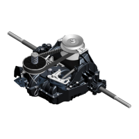
III- RT400 transaxle general description
The RT400 transaxle is design to provide an infinitely variable speed range thru one pedal control,
and a reverse operation thru an hand control. This transaxle also offer an integrate differential
function and a neutral automatic braking.
IV- How to use this manual
General Transmissions recommend, before tearing down the RT400 transaxle, to make sure that
you have a clean and organize work area, as well as the required specific tools.
General Transmissions also recommend to carefully read the general instructions provided in the
manual (p.5 to 6), before starting any reparation.
After detected the potential defective component, using the troubleshooting, follow the repair
procedures. It is necessary to complete the Preliminary operation, to be able to make the
Replacement operation (see troubleshooting p.7).
A defective component might cause premature wear or deterioration of other components. Make
sure that all necessary kit have been replaced.
For all service or repair operation, respect the shop and government safety rules.
 Loading...