QX System Installation Manual – Issue C
- 8 -
System Components
A QX system comprises of the following components:
1. A QX control unit, which processes all the alarm information from the detection points. Outputs
are provided to operate sounders, strobe and communication devices. Configuration information
is stored in EEPROM. The PX engineer manual details the features of the QX control panels.
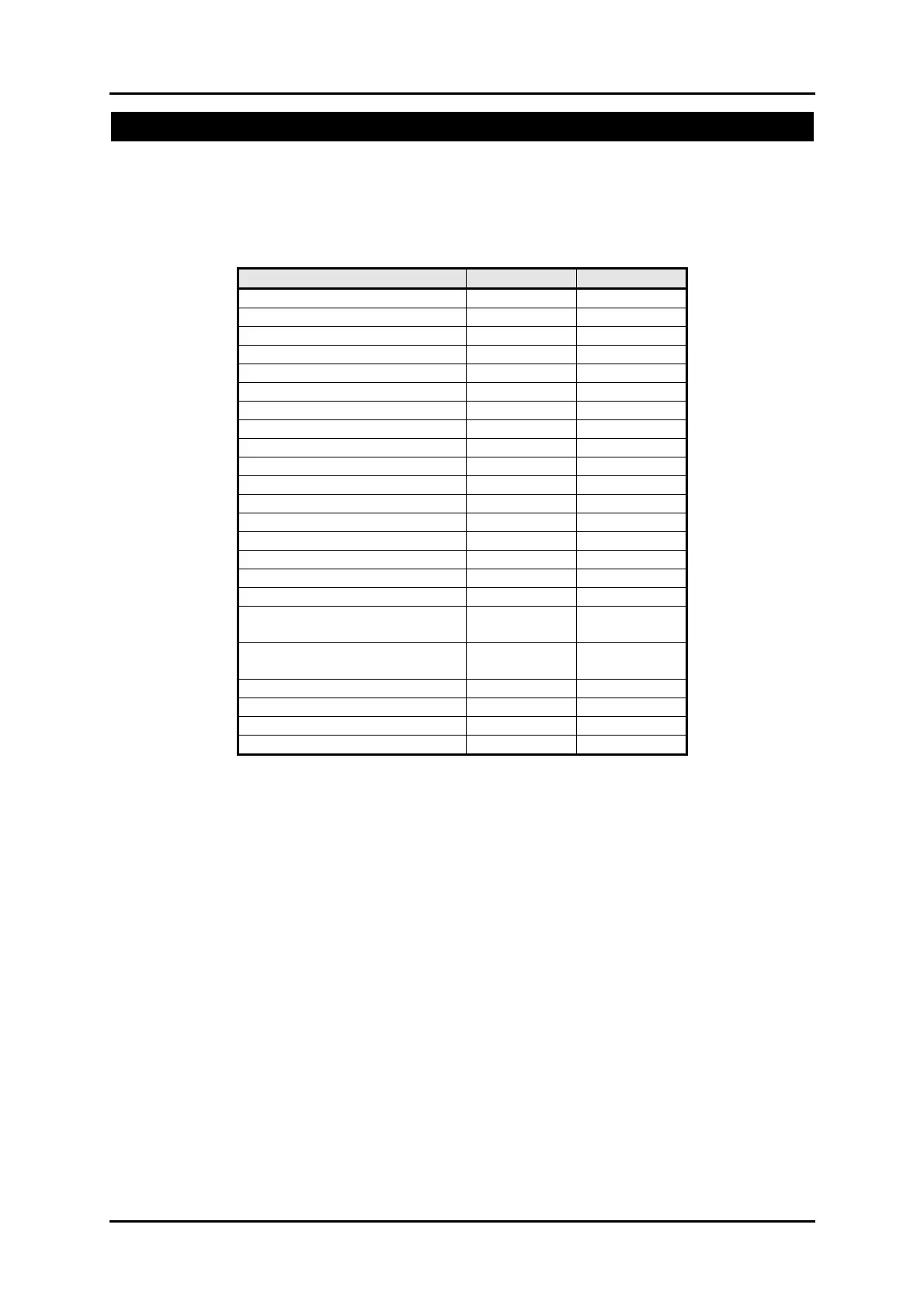
Feature QX18/QX18i QX34/QX34i
Max. Circuits 18 34
Max Concentrators 2 4
Circuit Doubling
Max. Panel Users 15 30
Areas 4 8
Set Groups 4 8
Max Keypads 4 8
Max Active keypads 2 2
Output Modules 1 2
Output functions 10 10
Serial/Data comms Modules 2 2
Responses 2 5
Tel Numbers 4 4
Schedules 4 4
Event Log Size 250 250
PSU Diagnostics Optional Optional
Deep discharge Optional Optional
Cct and company name text
descriptors
16 chars 16 chars
User, set group, conc & door
text descriptors
10 chars 10 chars
Copy
Pin of the day
Auto Sum/Win
Auto Set/Unset
The diagram on the following page shows the bus peripheral connections.
2. User interaction with the system is via LCD keypad. There must be at least 1 keypad on a
system. There are several types of LCD keypad available, which are detailed later.
3. Up to 10 detectors may be connected directly to the panel. Further detectors, up to the control
panel limit, may be connected to the system through concentrators on a 4-wire bus. Each
concentrator provides 8 additional circuits.
4. Optional equipment includes output modules each with 8 programmable outputs, Mimic module
and Data comms module for an Ethernet connection to a PC.


 To Next Page