6 of 15
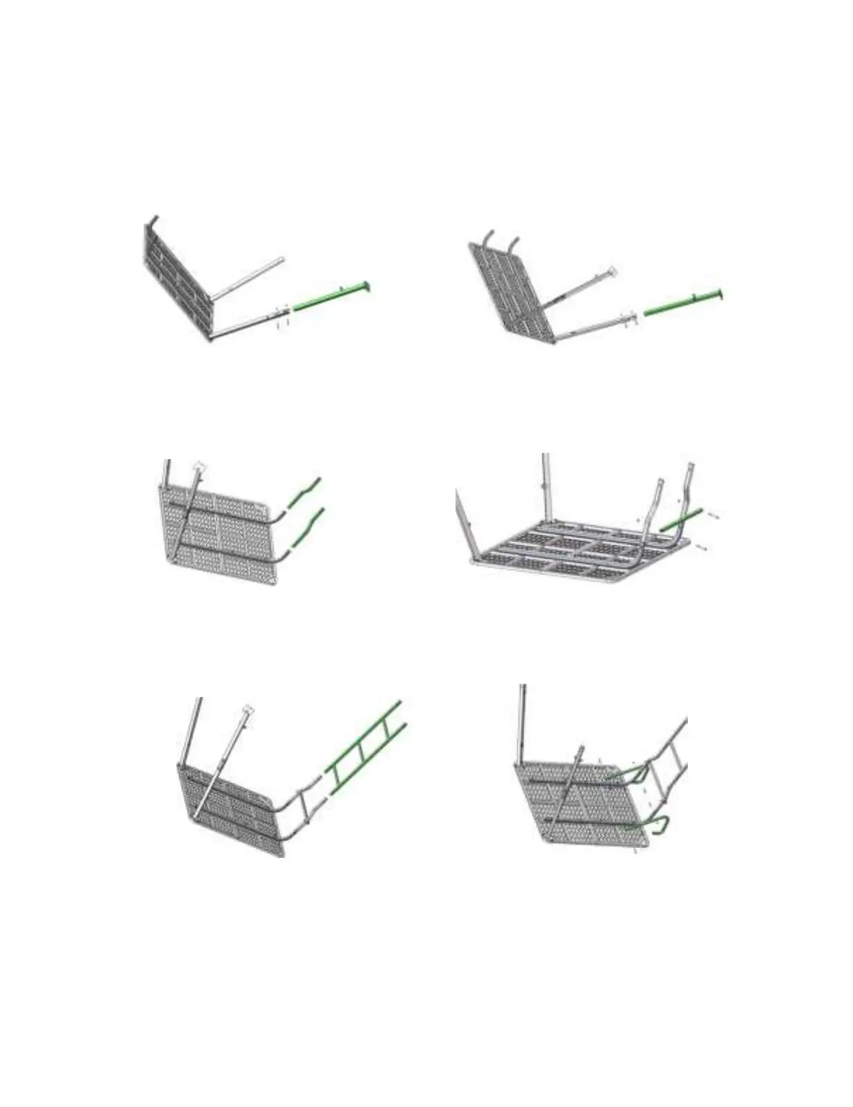
Step 5: Assemble the lower leg (TS305.28) and the attachment bracket brace (TS305.08) to the right upper leg
(TS305.21) by using two 1/4"-20×2-1/4" bolts (48271B) and two 1/4" lock nuts(48752B). Leave these hand tight
for now (Figure 5).
Step 6: Assemble the lower leg (TS305.28) and the attachment bracket brace (TS305.08) to the left upper leg
(TS305.09) by using two 1/4"-20×2-1/4" bolts (48271B) and two 1/4" lock nuts(48752B).Leave these hand tight
for now (Figure 6).
Figure 5 Figure 6
Step 7: Insert the two ladder extension tubes (TS305.20) into the two platform braces (TS305.18). (Figure 7).
Step 8: Attach the ladder step (TS305.19) to the two ladder extension tubes (TS305.20) by using two 1/4"-20×3"
bolts (48275B) and two 1/4" lock nuts(48752B). Leave these hand tight for now (Figure 8).
Figure 7 Figure 8
Step 9: Insert the ladder section
(
TS305.02
)
into the two ladder extension tubes (TS305.20). (Figure 9).
Step 10: Attach the two ladder hand rails (TS305.17) to the outside of two platform braces (TS305.18) by using
four 1/4"-20×2" bolts (48153B) and two 1/4" lock nuts (48752B). Leave these hand tight for now (Figure 10 ).
Figure 9 Figure 10