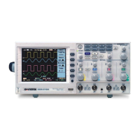
Do you have a question about the GW Instek GDS-2304A and is the answer not in the manual?
Explains safety symbols and provides essential guidelines for safe operation and handling of the GDS-2000A.
Details electrical input requirements, safety precautions for the power supply, and instructions for safe cleaning.
Explains display elements like channel indicators, waveform types, trigger status, and acquisition modes.
Provides an overview of various trigger types including Edge, Delay, Pulse Width, Video, Runt, Rise/Fall, and Timeout.
Lists the default factory settings for key oscilloscope functions like Acquire, Display, Channel, and Cursor.
Lists and defines various automatic measurements for voltage, current, time, and delay types.
Introduces math operations including basic arithmetic, FFT, and advanced functions for waveform analysis.
Covers acquisition process, modes (Sample, Peak Detect, Average), digital filter, and XY mode.
Introduces segmented memory for optimizing capture, covering display, navigation, and measurement of segments.
Details display settings like waveform appearance (dots/vectors), persistence, intensity, and graticule options.
Explains how to set horizontal scale, position, and waveform update modes (Normal, Roll, Zoom).
Guides on setting vertical scale, position, coupling modes, input impedance, and probe settings.
Details various trigger types (Edge, Delay, Pulse, Video) and common parameters like Source, Mode, and Slope.
Details the Go-NoGo test for waveform boundary checking, including conditions, actions, source, and tolerance settings.
Covers basic configuration for USB, RS-232C, Ethernet, Socket Server, and GPIB interfaces for remote control.
Introduces the built-in web server for viewing system info, network settings, and display images remotely.
Details the step-by-step procedure for performing vertical accuracy calibration on the oscilloscope.
Explains the method for compensating the oscilloscope probe for accurate signal measurements.
Lists model-specific electrical and performance specifications for the GDS-2000A series oscilloscopes.
| Channels | 4 |
|---|---|
| Bandwidth | 300 MHz |
| Vertical Resolution | 8 bits |
| Vertical Sensitivity | 1 mV/div to 10 V/div |
| Input Coupling | AC, DC, GND |
| Max Input Voltage | 400 V (DC + AC peak) |
| Sample Rate | 1 GSa/s |
| Display | 8-inch TFT LCD |
| Input Impedance | 1 MΩ |
| Trigger Modes | Edge, Pulse, Video |
| Interface | USB Host, USB Device, LAN |
| Timebase Range | 1 ns/div ~ 100 s/div |
| Power Supply | AC 100 V ~ 240 V, 50 Hz ~ 60 Hz |
| Memory Depth | 20 Mpts (Single Channel), 10 Mpts (per Channel) |
