EasyManua.ls Logo

Gymna Pulson 330 - User Manual

Gymna Pulson 330
49 pages
Print Icon
To Next Page IconTo Next Page
Loading...
1. Contents
1. Contents ..........................................................1
2. Preface ...........................................................1
3. Introduction ......................................................3
4. Important remarks .................................................4
5. General technical data. ...........................................6
6. Block diagram. ....................................................7
7. Operation panel ...................................................8
8. Right side panel. ................................................10
9. Power supply. ....................................................11
10. Microcontroller circuits. .......................................13
10.1 The microprocessor (µp).......................................13
10.2 Microprocessor guard components...............................13
10.3 I²C bus.......................................................13
10.4 Relay 4 (RLY4)................................................14
10.5 Microprocessor (µp) pin description...........................14
11. Keyboard. .......................................................17
12. US power and output stage. ......................................19
12.1 Measuring and displaying US power.............................19
12.2 Automatic power density limitation............................20
12.3 Switched mode power supply....................................20
12.4 The ADDA convertor............................................20
12.5 Output frequency generation...................................21
12.6 Relay drivers.................................................21
13. US output stage .................................................23
13.1 Output voltage and current measurement........................24
13.1.1 Voltage measurement. ......................................24
13.1.2 Current measurement. ......................................24
13.2 Relay circuits................................................24
13.3 Contact control...............................................25
13.4 Cable fraction detection......................................25
14. The display circuit. ............................................28
14.1 Display circuits..............................................28
14.2 Display warnings..............................................28
15. Error codes. ....................................................30
16. Measuring points. ...............................................31
17. Replacement procedures. .........................................32
17.1 Bottom plate..................................................32
17.2 Main PC board (ELUL 004-L100-V20).............................32
17.3 Ultrasound PC board (ELUL 004-L300-V30).......................32
17.4 Display PCB (ELUL 004-L400-V20)...............................32
17.5 Power transformer.............................................33
18. Repairing PC boards. ............................................34
18.1 Which tools are necessary ?...................................34
18.2 Which procedure has to be followed?...........................34
19. Storage and transport. ..........................................35
20. Microprocessor versions and upgrades. ...........................36
20.1 The upgrade routine...........................................36
20.2 Microprocessor software versions..............................36
21. The ultrasound heads. ...........................................37
22. Returning defective parts. ......................................39
22.1 Guarantee claims..............................................39
22.2 Defective parts...............................................39
22.3 Filling out the ‘Request Return Defective Parts’ form.........39
23. PCB layouts. ....................................................42
24. Spare parts. ....................................................46
2. Preface
As in every field, technology moves fast in the area of electro-
medical equipment.
Both electronically and medically, immense progress has been made over
the last couple of years.
Page 1
Question and Answer IconNeed help?

Do you have a question about the Gymna Pulson 330 and is the answer not in the manual?

Summary

2. Preface

3. Introduction

4. Important remarks

Safety Precautions and Responsibilities

Emphasizes technical background requirement and Gymna's disclaimer for unauthorized actions.

Data Registration Requirements

Details required data for distributors: instrument, customer, and service activity information.

5. General technical data.

Treatment Unit Technical Specifications

Details mains voltage, frequency, fuses, current, dimensions, weight, labels, and IEC 601-1 compliance.

Ultrasound Head Specifications

Specifies surface area and maximum output power for 1 MHz and 3 MHz ultrasound heads.

6. Block diagram.

7. Operation panel

US Power Display Function

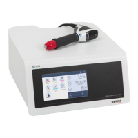
Displays the US power intensity in W/cm² during operation.

Treatment Time Display Function

Shows treatment time in minutes and seconds, with timer functionality.

Intensity Control Keys

Includes intensity up and down keys to adjust output levels.

Output Mode Selection Switch

Allows selection between continuous and pulsed ultrasound output modes.

1;3 MHz Head Selection Key

Key to switch between 1MHz and 3MHz ultrasound heads, with operational notes.

Timer Adjustment Switches

Includes timer down and timer up switches for setting treatment duration.

8. Right side panel.

Right Side Panel: Output Connectors

Describes CON1 and CON2 for connecting 1/3 MHz ultrasound heads.

Right Side Panel: Mains Entrance and Supply

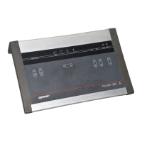
Covers mains connection, voltage check, and serial number plate information.

Right Side Panel: Combination Therapy Plug

Explains the plug for linking the Pulson 330 with other GYMNA apparatus.

Right Side Panel: Power Switch

Indicates the power switch and its indicator light.

9. Power supply.

Power Supply Output Voltages

Lists the regulated (VCC, VEE) and unregulated (V27) output voltages and their specifications.

10. Microcontroller circuits.

10.1 Microprocessor (μp) Overview

Describes the Z86E21 microcontroller, its ROM, RAM, and clock speed.

10.2 Microprocessor Guard Components

Explains components like U2 (supervisor IC) and U6 (protection IC) for monitoring the microprocessor.

10.3 I²C Bus Interface Details

Details the I²C bus used for communication with Eeprom and ADDA IC.

10.4 Relay 4 (RLY4) Functionality

10.5 Microprocessor Pin Descriptions

Lists and describes the function of various pins on the microprocessor.

11. Keyboard.

Keyboard Functionality

Details the 7-key keyboard, its connections, and HF-noise filtering.

Version Check Procedure

Describes how the unit detects and checks hardware and software versions on startup.

12. US power and output stage.

12.1 US Power Measurement and Display

Explains how US power is measured, calculated, and displayed, considering head efficiency.

12.2 Automatic Power Density Limitation

Describes automatic reduction of US output density to prevent exceeding limits.

12.3 Switched Mode Power Supply Circuit

Details the switched mode power supply circuit (U1) and its regulation mechanism.

12.4 ADDA Converter Functionality

Explains the ADDA converter (U15) and its role in measuring voltage and current.

12.5 Output Frequency Generation Circuit

Describes frequency generation using dividers and multiplexers for 1MHz and 3MHz.

12.6 Relay Driver Transistors

Explains the function of transistors Q6, Q7, Q8 as drivers for relays.

13. US output stage

13.1 Output Voltage and Current Measurement

Covers circuits for measuring output voltage and current using peak values.

13.2 Relay Circuit Functions

Describes RLY1, RLY2, and RLY3 for switching outputs and detecting head size.

13.3 Contact Quality Control

Explains contact detection and management, with indicators for insufficient contact.

13.4 Cable Fraction Detection

Describes detection of cable fractures in US heads and the 'Cab' error.

14. The Display Circuit

14.1 Display Circuit Details

Explains display PCB connection via I2C bus and use of multiplexers/transistors.

14.2 Display Warnings and Indicators

Lists and explains warnings like USH, flashing intensity, and CNT.

15. Error Codes

Error Code ERR 1: ROM Check Fail

Microprocessor Eeprom failure; requires microprocessor replacement and upgrade.

Error Code ERR 2: Eeprom Checksum Fail

Checksum mismatch; requires Eeprom replacement and recalibration.

Error Code ERR 3;4: Eeprom Fail

Eeprom read or write failure; requires Eeprom replacement and recalibration.

Error Code Cab: Cable Fracture

Signals a broken cable in the treatment head, requiring replacement.

Error Code USH: Connection;Crystal Issues

Indicates connection issues or crystal damage; check connections and clean crystal.

16. Measuring Points

16.1 Cable Fraction Detection Signals

Explains signal measurements for detecting cable fractures using S1 and S2 signals.

17. Replacement Procedures

17.1 Bottom Plate Replacement Procedure

Details bottom plate removal/installation, including earth cable connection.

17.2 Main PC Board Replacement

Provides removal/installation steps for the Main PC board, emphasizing correct cable connections.

17.3 Ultrasound PC Board Replacement

Details removal/installation for Ultrasound PC board, stressing correct cable connections.

17.4 Display PCB Replacement Procedure

Outlines procedure to remove and open the Display PCB enclosure for access.

17.5 Power Transformer Replacement

18. Repairing PC Boards

18.1 Required Tools for PC Board Repair

Lists essential test equipment and tools for PC board repair and calibration.

18.2 Repair Procedure and Calibration

Outlines repair steps, including safety tests, data registration, and calibration needs.

19. Storage and Transport

20. Microprocessor Versions and Upgrades

20.1 Microprocessor Upgrade Routine

Details the step-by-step procedure for upgrading the microprocessor software.

20.2 Microprocessor Software Version History

Lists historical software versions and release dates, with remarks on upgrade necessity.

21. The Ultrasound Heads

1 MHz Ultrasound Head Details

Shows the 1 MHz head, its part number, and wiring details for efficiency resistance.

3 MHz Ultrasound Head Details

Shows the 3 MHz head, its part number, and wiring details for efficiency resistance.

22. Returning Defective Parts

22.1 Guarantee Claims Process

Details process for guarantee claims, requiring GYMNA approval and a PARTS RETURN TAG.

22.2 Defective Parts Return Process

Explains returning defective parts, needing GYMNA approval and proper tagging.

22.3 Filling Out Return Forms

Instructs on completing the defective parts return form and submitting it via fax.

24. Spare Parts Information

23.1 Ordering Spare Parts

Specifies required data (part number, description, quantity) for ordering spare parts.

Gymna Pulson 330 Specifications

General IconGeneral
BrandGymna
ModelPulson 330
CategoryMedical Equipment
LanguageEnglish

Related product manuals