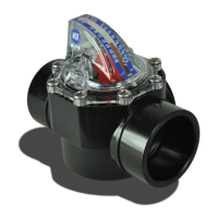
1.0 DESCRIPTION
FlowVis® is a revolutionary Patent Pending product that converts a standard Check
Valve into a Flow Meter and Check Valve.
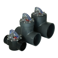
The product is currently available in two formats:
a) Retro t to install to an existing Jandy® (7305) 2” by 21/2” Check Valve body -
FV-J.
b) A complete Check Valve body assembled with FlowVis® - FV-C.
c) A complete Check Valve body assembled with FlowVis® and a safety apper, as
described in section 6 of this manual.
The Retro t kit comprises a fully assembled FlowVis® lid, calibrated spring, pin, indicator
arm, ‘O’-ring and calibrated scale. Installation simply requires the removal of the eight
screws securing the existing lid, installing the new ‘O’-ring and securing the FlowVis®
with the original eight screws.
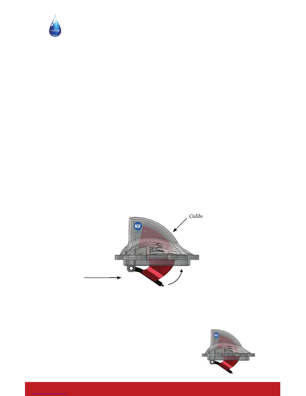
2.0 CONCEPT
As ow increases, the check valve apper extends towards its fully open position. The
angular position of the apper is determined by the ow through the valve body. A
calibrated scale on the valve lid provides an accurate reading of ow.
FlowVis® - INSTRUCTION MANUAL Page 3
Flow
Calibrated Scale
3.0 NSF50
FlowVis® model FV-C has been tested and certi ed as a Flow Meter to NSF 50.