EasyManua.ls Logo

H2flow FlowVis FV-C User Manual

H2flow FlowVis FV-C
16 pages
To Next Page IconTo Next Page
Page #1 background imageLoading...
Page #1 background image
FlowVis
®
FlowVis
®
Flow Meter
English
Rev.4.5
Operating Manual
2.5” / DN50/65, 3” / DN80 and
4” / DN100 models
FlowVis® retrofi t model
DESCRIPTION
FlowVis® is a revolutionary, patented solution for accurate and
reliable fl ow rate measurement in fresh water applications
such as swimming pools, spas, fountains, water features, and
solar systems.
Using a design that is based on ‘mass fl ow’ principles, the
FlowVis® provides many benefi ts that include:
Ease of installation without the need to have 15x of
straight pipe
Installation fl exibility that allows orientation in any
position, e.g., horizontal, vertical or even upside-down
Long life without sticking fl oats or paddle wheels
Combined Flow Meter and Check Valve in all models
except FV-C-S, FV-C-Saline, FV-3, FV-L-DN80, FV-4 and
FV-L-DN100.
CONCEPT
As fl ow increases, the check valve or safety fl apper moves
forward toward its fully open position. The fl apper’s angular
position is directly related to fl ow rate through the valve body
/ Tee. A calibrated scale on the valve’s lid provides a highly
accurate reading of the fl ow rate.
Calibrated Scale
Flow
www.h2fl ow.net Tel: 888-635-0296 (Toll Free) OR (+1) 419-841-7774 (International)
IMPORTANT NOTE: For the most up-to-date version of this manual, please visit www.h2fl ow.net/product-literature
Question and Answer IconNeed help?

Do you have a question about the H2flow FlowVis FV-C and is the answer not in the manual?

H2flow FlowVis FV-C Specifications

General IconGeneral
Pipe Size1.5 - 12 inch
MaterialPVC, CPVC
Max Pressure232 PSI
Max Temperature140°F
Accuracy±2%
Pipe Diameter Range1.5 - 12 inch
Operating Temperature32°F to 140°F
Storage Temperature-40°F to 140°F

Summary

FlowVis Models Overview

Safety Information and Chlorine Feeders

Warnings and Valve Body Feature

VGBA Compliance

Discusses VGBA compliance and backup anti-entrapment systems for pool safety.

Installation Guidelines

Lid Assembly and Operation

Tightening Lid Screws Procedure

Step-by-step procedure for tightening lid screws, including torque specifications.

Flow Range Specifications

Table detailing minimum and maximum flow rates for various FlowVis models.

Head Loss Data for FV-C and FV-C-S Models

Head Loss Data for Additional Models

Operation and Maintenance

Reading Flow Rate Accurately

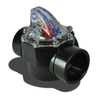
Guidance on proper viewing angle to avoid parallax error when reading the scale.

Flow Rate and Velocity Indication

Explains how the scale indicates flow rate and velocity using color bands.

Maintenance Checks and Remedies

Lists common conditions, checks, and remedies for FlowVis maintenance.

Technical Data and Materials

Product Warranty Information

Warranty Definition and Eligibility

Defines the 3-year warranty, its eligibility, and how to obtain service.

Warranty Exclusions and Charges

Lists conditions that void the warranty and details associated charges.

Warranty Disclaimer

States express and implied warranties, disclaiming liability for consequential damages.
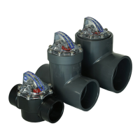
Related product manuals