5-33
5 Appendix D Cooling system
To dissipate heat timely and enhance system stability, the switch uses a high-performance cooling
system. Consider the site ventilation design when you plan the installation site for the switch.
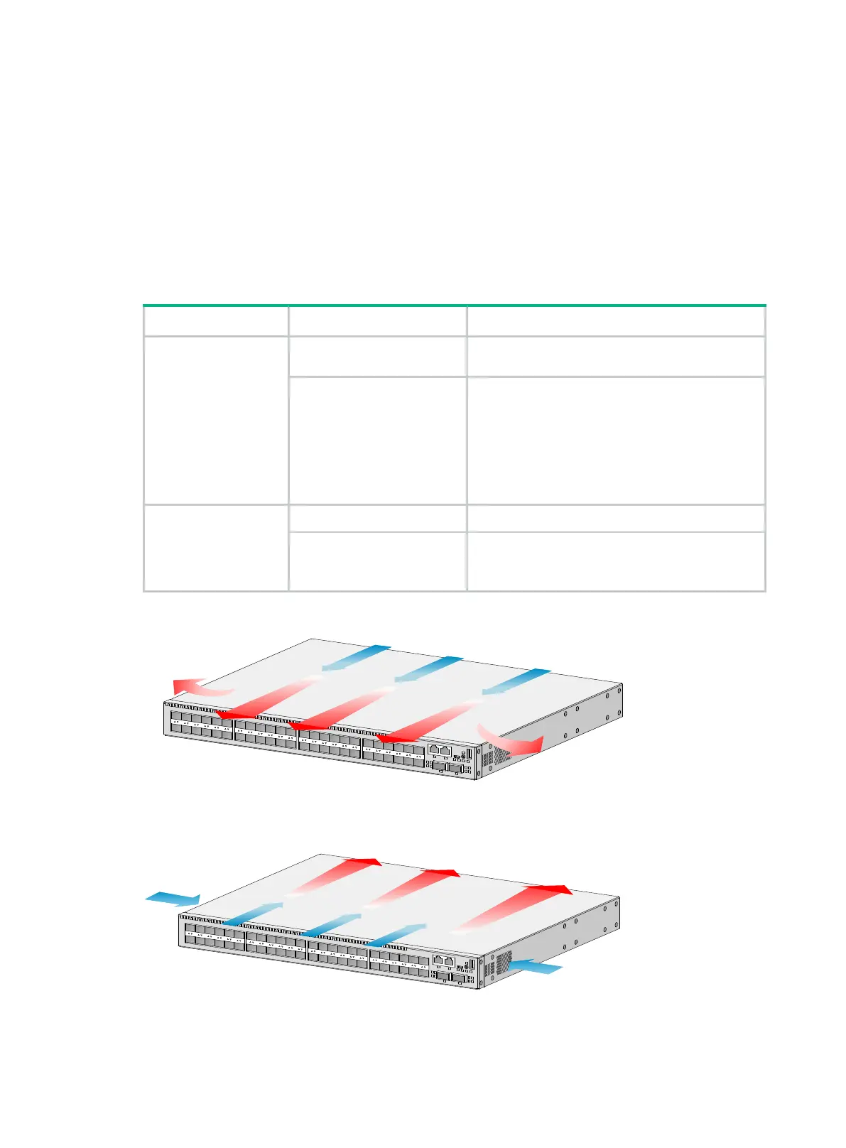
The switch uses removable fan trays. They provide airflow from the port side to the power supply
side or from power supply side to the port side by using different types of fan trays. You must install
all fan trays of the same model for the switch. Table5-1 describes fan trays available for the switch.
Table5-1 Fan trays available for the switches
Device model Fan tray Airflow direction
S6520X-30QC-EI
S6520X-54QC-EI
S6520X-30HC-EI
S6520X-54HC-EI
S6520X-30QC-HI
S6520X-54QC-HI
S6520X-30HC-HI
S6520X-54HC-HI
LSWM1FANSCE
From the power supply side to the port side and
chassis sides
LSWM1FANSCBE
From the port side and chassis sides to the power
supply side
S6520X-30HF-EI
S6520X-54HF-EI
S6520X-30HF-HI
S6520X-54HF-HI
LSPM1FANSA-SN From the power supply side to the port side
LSPM1FANSB-SN From the port side to the power supply side
Figure5-1 Airflow direction (S6520X-54QC-EI)
LS W M 1FA N SC E
LS W M 1FA N SC B E

 Loading...


