Do you have a question about the Hach ULTRATURB sc and is the answer not in the manual?
Detailed dimensions of the ULTRATURB sc unit, including diagrams and measurements.
Crucial safety instructions, hazard information, and precautionary labels for safe operation.
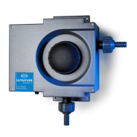
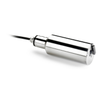
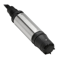
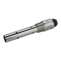
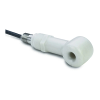
Describes the primary uses and versions of the ULTRATURB sc sensor in water analysis.
Explains the nephelometric scattered light technique used by the sensor.
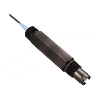
Guidance on careful handling of the sensor due to its optical and electronic assemblies.
Lists all components included in the ULTRATURB sc sensor package.
Instructions for performing a basic function check after unpacking and before installation.
Guidance on selecting an installation location and correctly mounting the instrument.
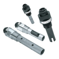
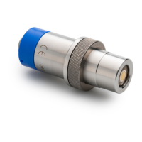
Details on instrument connectors, pipe threads, and diaphragm plate selection for sample connection.
Visual representation and component list of the ULTRATURB sc instrument layout.
Step-by-step instructions for connecting the sensor cable to the controller, including pin assignments.
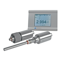
How to operate the sensor with sc controllers and navigate through their functions.
Guide to configuring sensor settings such as name, units, measurement intervals, and response time.
Information on how data and events are logged by the sensor and controller.
Overview of the menu structure, including SENSOR DIAG.
Details on error and warning lists within the SENSOR DIAG menu.
Detailed breakdown of SENSOR SETUP options like WIPE, VERIFY, CALIBRATE, CONFIGURE.
Detailed steps for calibrating the sensor using a standard liquid solution.
Procedure for verifying sensor calibration using a dry standard CVM module.
Instructions on how to set the zero point for the sensor calibration.
A summary table outlining recommended maintenance tasks and their intervals.
Step-by-step guide for cleaning the sensor's measuring chamber to ensure accurate readings.
Instructions for replacing wiper profiles on the plus and seawater versions of the sensor.
Guidance on replacing desiccant bags to protect optical and electronic components from moisture.
Procedures for monitoring test equipment calibration using formazine solutions.
Lists common sensor error messages, their causes, and recommended rectification steps.
Lists common sensor warning messages, their causes, and recommended actions.
Catalog of available ULTRATURB sc sensor models with different cable lengths.
Catalog of essential replacement parts for the sensor, like wiper profiles and desiccant.
List of available accessories, including extension cables and calibration equipment.
Details the conditions and situations not covered by the product's warranty.
Outlines the exclusive remedies available for warranty breaches and limits liability.
Contact details for HACH Company's main headquarters in Loveland, Colorado, USA.
Contact information for HACH Company's global repair service network.
A comprehensive list of ModBUS registers for the sensor, including group name, register, type, length, R/W, and description.
| Product Type | Turbidity Sensor |
|---|---|
| Measurement Range | 0 to 1000 NTU |
| Light Source | LED |
| Wavelength | 860 nm |
| Storage Temperature | -20 to 60 °C (-4 to 140 °F) |
| Protection Rating | IP68 |
| Accuracy | ±2% of reading or ±0.01 NTU |
| Operating Temperature | 0 to 50°C (32 to 122°F) |
| Cable Length | 10 m |
| Output | 4-20 mA |
| Weight | 1.5 kg |