2
3
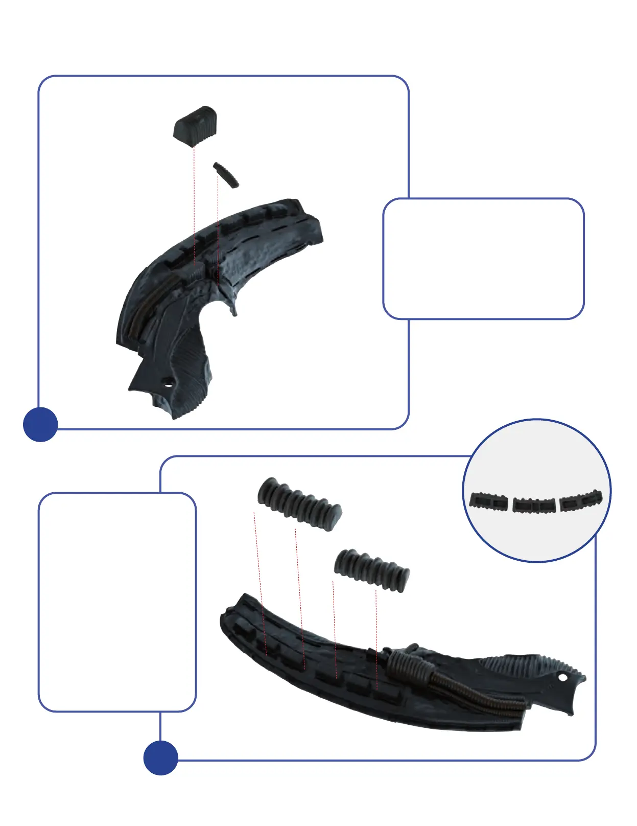
KIT 7: CENTRE-LEFT SECTION OF THE HEAD
2
3
6-7
6-6
6-1
7-1
7-3
7-2
7-1
7-2
7-3
7-4
Examine the inset
picture (right) to help you
differentiate between
parts 7-2, 7-3 and 7-4,
each of which has a
slightly different internal
layout. After checking
that each piece fits
correctly in the place
indicated on the Centre-
left Section of the Head
7-1, apply a dab of glue
to Pipes 1 and 2 (7-2 and
7-3) and fit them over
the rectangular blocks as
shown in the photo.
Turn the assembly over and take
the two Pipes 6-6 and 6-7 which
were supplied with the previous kit.
Test-fit these in position and when
certain of a good fit, glue firmly in
place. Part 6-7 fits across the join
between Head parts 6-1 and 7-1.