55
9
10
10-4
11-5
11-4
7-1
2-1
12-1
9-1
7-8
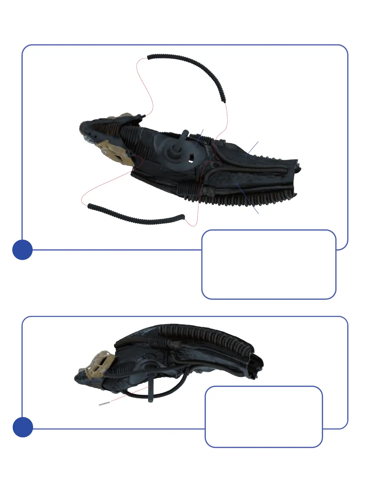
KIT 12: THE HEAD AND SKULL
Turn the head assembly upside down and
take Pipes 7-8 and 10-4 which were
supplied with kits 7 and 10 respectively.
One end of part 7-8 has a peg which
inserts into a hole in part 7-1. The other
end fits onto the peg on part 2-1, as
shown. Glue in place. Repeat the process
to fit the right hand Pipe 10-4.
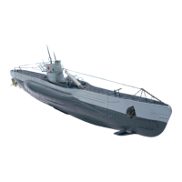
Take the Pin 11-5 which was
supplied with kit 11. Insert it
temporarily into the central hole
of the ball joint Rod 11-4. The
smooth end of the pin should be
inserted first. Use masking tape, or
similar, to hold it in place.