hager
Fitting, electrical connection and operation
Seite 7 von 130
Connecting the device in order to supply the device electronics and the DALI interface with
power
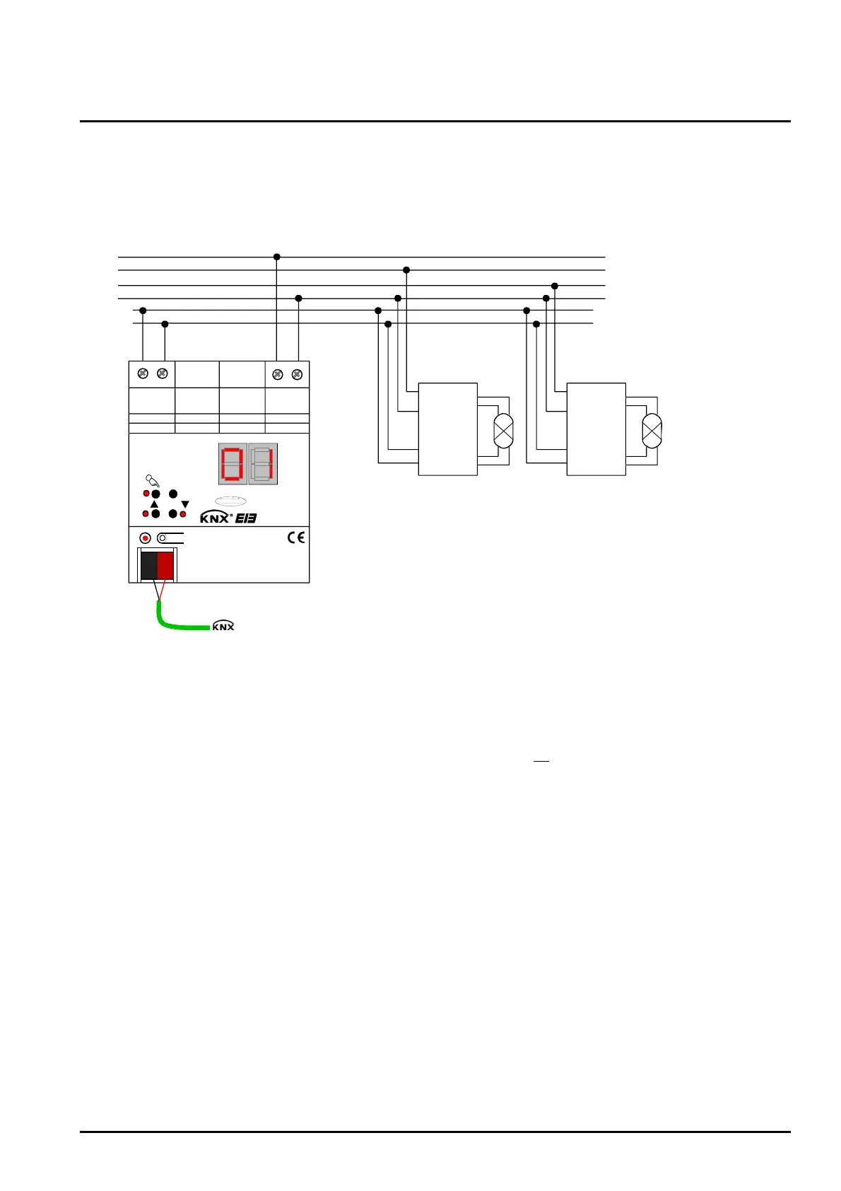
Connect the mains voltage and the DALI system as shown in fig. 1 (connection example).
L1
L3
L2
N
da
da
L
N
da
da
L
N
da
da
ALL OFF
ON/ OFF/
da+ da- L
N
D A L I
DALI device
1
DALI device
2
. . .
(max. 64)
red
black
EIB
Fig. 1: Electrical connection of mains voltage and the DALI interface
• The DALI system voltage is a functional extra-low voltage (FELV). Thus, the DALI interface has to be
treated like a live line in compliance with the applicable installation prescriptions. The DALI Gateway
supplies the system voltage. The installation has to ensure that all
mains voltages of the connected
DALI devices as well as the mains voltage supply of the DALI Gateway will be switched off when
activating a DALI section.
• For a better overview in the installation it is recommended to pay attention to the polarity of the DALI
line. Basically, the compliance with the DALI polarity depends on the DALI devices that are used.
• DALI devices (max. of 64) can be connected to different phase conductors (L1, L2, L3).